Good afternoon. I bought a new “sculpfun ir-2 1064” laser head to replace my Sculpfun s9 and I would like to connect it to my Cnc board controller. Can someone help me please?
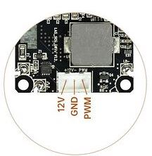
The S9 has the following order:
12V-GND-PWM (image attached).
But I don’t know the order in IR-2.
Thank you so much.
I believe that the image did not board and remained on land. ![]()
![]()
I found this video on youtube were, at 3:40 minute, you can see a modification from S9 to S10 (if I’m not mistaken) that needs a cable. Maybe through this cable you can understand how the connections are made.
But I didn’t find anything else concrete in the brief research I did.
Thanks for responding, I did see that video, but I have it mounted on an Arduino with a CNC SHIELD, so what I need is to know what each of those pins correspond to, I hope my question is understood.
Yes, I understood, but I got lost in the answer. sorry. ![]()
Knowing the connections in a sculpfun makes it easy…
I understand, I hope you find a solution, I’m afraid of connecting it and it becoming defective.
Sculpfun’s product page shows an adapter cable (also shown in your picture) that has 1-to-1 pinning. So you should be able to compare the pin-out on your S9 to what you’ve got now.
Possible Wrong: See Below
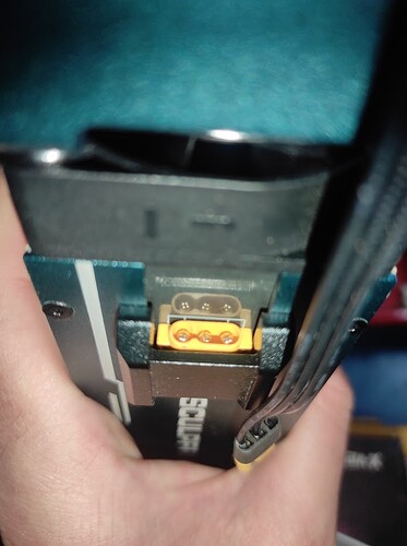
From the two pictures that you’ve included and Sculpfun’s picture that includes the other end of that adapter cable, it looks like (on the yellow cable end) that +24V is the pin on it’s own next to the indent in the plug. Centre is ground, the other one is signal (same order as your other laser).
Note that the IR laser is 24 volt, not 12 volt.**
As Daryl pointed out, the pin order is the same as the other laser heads. You can find an image of the pinout here: Sculpfun S30 Ultra Series - Diode Laser Wiki
And as he also noted, you need a 24V power supply. The original mainboard can handle this without any issues, but make sure any other periphery you added can handle this too.
Melvin’s pictures show VCC and ground in the grouping of two pins and the PWM signal in the single pin group (groupings by the indent). I’d go with what his pictures show. To be safe, you could just check it with a multimeter. One will have the +24V (VCC) voltage, the other won’t.
Thank you very much for your reply, it is becoming a little clearer for me, the module comes with its original 24v power supply.
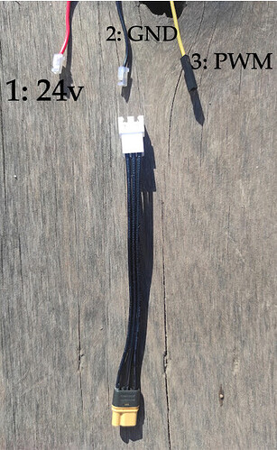
The way I have it is without a final connector, I have the 3 cables
cable 1: 24v
cable 2: GND
cable 3: PWM
and I should connect them to the adapter cable that comes with the IR-2.
I am attaching an image, I hope it is understood. ![]()
![]()
I edited because there was a mistake
Again, according to the pinout in Melvin’s pictures on his website, the 24V (VCC) and Ground go to the side of the plug that is divided from the other pin by the indent (in the yellow connector). So, in your picture, swap the positions of #1 and #3.
Thank you very much for your help and time in responding, as soon as I can connect it I will let you know!!! Thank you again!!!
Good afternoon, I was able to connect it there and it worked, or at least it didn’t burn!!! It moves and takes the engraving or cutting order, now I have to configure it correctly, because the pointer stays on (perhaps it is normal) and when sending the orders they do not have the force (it moves but does not record or cut).
Thank you very much, the solution to the request is resolved!


