I’m working on finding the best way to incorporate a Universal ILS 12.15 which was donated to our makerspace and I’m exploring the idea of “printing” from Lightburn to the Universal. The main reason is that most of our users know how to use Lightburn and I would consider our makerspace a “Lightburn shop” While we can certainly set it up to work from Inkscape or Corel Draw, that impacts the learning curve. The idea I had is to see if we could use the Print function in Lightburn to push the job directly to the print driver that directs the action of the Universal. However, it looks like the line width is too wide for what the Universal is expecting as a vector cut. Is there any way to control the line width Lightburn uses when generating a print job outside of running it through a secondary software to accomplish that function (i.e. export from Lightburn as SVG and then open in Inkscape and print from there).
It looks to me like the line width coming out of Lightburn is 0.050mm and the Universal won’t execute a vector cut on anything wider than 0.025mm.
I know that Lightburn doesn’t officially support Universal lasers, but I thought it would be good to explore if there’s any way to adjust things to make it work in some fashion. Thanks in advance.
Lightburn is going to create the codes needed for a specif controller. As this controller isn’t one that’s supported, that I know of, it’s likely you will have to export it to some other piece of software.
Lightburn creates vector files that only have the path, there is no line size involved. My fiber can have a 30 micron (0.030mm) beam, the co2 is about 200 microns (0.20mm). Both still work fine on either machine, but the fiber is capable of a smaller of more detailed engraving.
I don’t know what drives the controller, if it’s just a vector file sent or there is some code generation for a vector file. My Ruida has codes generated specifically for a Ruida, this is generally how Lightburn operates.
Maybe someone from @LightBurn can answer your question with more accuracy as they know the internals much better than I.
The OP is referring to the File>Print (Keep Colors) function in LB. He is correct in what he is saying regarding stroke width using the File>Print (Keep Colors) function.
I have a Universal Laser Systems VLS6.60 and ULS lasers use a print driver to send files to their UCP software that runs the laser.
I use Adobe Illustrator and I set the stroke width in AI to 0.001”. CorelDraw has a stroke width called “hairline” that many ULS users use.
You are correct that LB does not have a stroke width when you are designing, but it does when you File>Print (Keep Colors). You can verify by printing to a PDF file and opening the PDF in a graphics program like Adobe Illustrator or CorelDraw.
If LB could File>Print (Keep Colors) the correct stroke width, then it would work correctly.
Thanks for the clarification. I’m not a user of anything that makes proprietary software to be able to use. I realize this isn’t that precisely, but I run Ubuntu and most of this software only runs on Windows some on Macs
Wonder what it does, it would have to generate codes for the controller, I’d think …?
Thanks @RalphU, one follow up question, I’m not seeing the option to set the stroke width when using File > Print (Keep Colors), I just get a windows print dialog and have an option to pull up the UCP settings panel. Can you share with me what you’re seeing so I can figure out where I’m missing it?
If it helps to know, I’m on LB 2.0.05 currently and thank you so much!
I was able to get it to work with this workaround on a PC in Lightburn
File>Print (Keep Colors)
Select “Microsoft Print to PDF
Select the “Preferences” button
Switch Orientation to “Landscape”
Select the “Advanced” button
Change the paper size to the “D size sheet”
Select “OK” button
Select “OK” button
Select “Print” button
Enter a PDF filename
Select the “OK” button
Open Acrobat with the PDF file
File>Print
Select the UCP driver and scale none
Select “OK” button
Switch to UPC software and it should be OK
Edit: If you have CorelDraw on the computer that runs the laser, you could just have the users do steps 1 thru 11, then open the PDF file in CorelDraw and send it to the laser. I tested it with Acrobat, Adobe Illustrator and CorelDraw. They all worked. I could not get it to work with Inkscape.
I was able to get it to work with this workaround on a PC in Lightburn
Thanks so much. It looks like that works as an option (testing locally, it looks like the UCP ends up with a vector design after going through these steps, in the “view job” window, so very promising), I need to fully test it out with the system when I’m onsite later this week.
The Corel Draw idea is a good one, but we don’t currently have a license for it for this project.
Thanks for the thought Colin. We do know that Corel Draw works, but from a long-term standpoint and a cost perspective, having two licensed pieces of software to get the laser operational and multiple steps isn’t optimal. I’d like to try and use Lightburn and have as few intermediary steps or additional software costs as possible. If we were going to go the Corel Draw route, then we’d just not use Lightburn at all for this machine and use Corel, but the idea is to see if we could use the Print function in Lightburn to push the job directly to the print driver that directs the action of the Universal.
I was able to get it to work with the new free program Affinity 3. I exported a SVG out of LB, and imported it into Affinity 3. You do have to select all of your score lines ( I use BLUE ) and cut lines ( I use RED ), and switch their stroke width to 0.001 inch in Affinity 3. Then when you control P and send the file to the UCP software, it imports correctly.
It would be nice if LB had a setting under file exports for SVG that allowed you to change the stroke width to something other than 0.050000mm like you mentioned previously.
You could teach your users to open the exported SVG file from LB into a text editor, and change all occurrences of 0.050000mm to 0.0254 ( you don’t need the added mm at the end) and then save. Affinity doesn’t like the added mm in the SVG file.
I used notepad++ on a PC and it is pretty easy. Then, you open the SVG into Affinity, and control P to the UCP. I attached my test SVG file.
I tried your suggestion, but it is only allowing me to key in a value to 2 decimal places. I cannot get it to work correctly with just 2 decimal places. I think for a Universal Laser Systems UCP software, the value would be 0.0254
If I set the value to 0.01, and print to a PDF file, I can then send the PDF file to the Universal Laser Systems UCP software, and it works
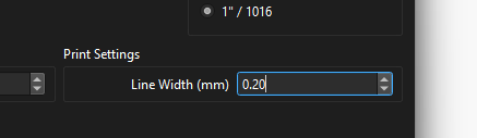
This is very exciting. I tried to grab the latest RC, but it wasn’t available (RC3), but I grabbed and installed v2.1.00-RC-1 and I see the option and set the value to 0.02 (the ILS documentation says the line has to be 0.0254mm or thinner, so I figured 0.02 should work) however, it looks like the actual line width in the print file generated is wider than that. My best guess is that it’s coming out closer to 0.16mm in width.
It might just be an issue with RC1, but this is a really exciting option if it works!
Steps to reproduce:
Open LB RC1 and select Edit > Settings > Import/Export > Print Settings: Line Width(mm) value=0.02 or 0.01 and click Ok
Draw a square with the Create Rectangle tool
Select File > Print (Keep Colors)
Print to UCP control panel and test cut, OR alternately, print to PDF and analyze the line width in another program.
I think it’s great to get it extended to 3 decimal places, 100%. I guess my thought though is, if the UCP documentation for the Universal laser system says that the line width has to be 0.0254mm or thinner to be considered a vector cut, and I set it to 0.02 or 0.01 in RC1 version of LB and it doesn’t look like it’s being interpreted as vector because the line width isn’t thin enough, doesn’t that mean there’s an issue or am I thinking about the wrong thing here.