We’ve updated this to .000 precision for the next RC
1 Like
@Colin I just tested the Print (Keep Colors) with the Universal Laser Systems UCP software and when I set Line Width (mm) to 0.025, it would not send the colored lines I was using - Red and Blue.
Like @Brinohm mentioned earlier - from the Universal Manual - “Vectors must have a line width of .001” (.0254 mm) or less, everything else will be treated as raster objects.”
I tried setting the Line Width smaller than 0.025, and I couldn’t get it to work.
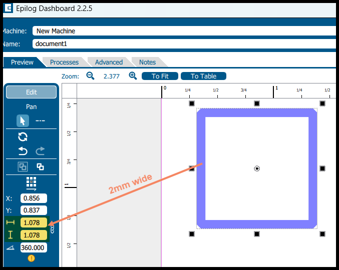
I know that the Line Width from LB is working, because I set the Line Width to it’s highest allowed value (2mm), and it raster engraved with my laser at 2mm wide. Kind of a nice affect.
I also tested the Print (Keep Colors) with the Epilog Dashboard software using a Line Width of 2mm, and it also created the 2mm wide line width.
@Colin would you be able to make the value at least 4 or 5 decimal places? Sorry for my previous confusion on the 3 decimal places.
Thanks
First, thanks for such a quick turnaround on a release candidate to test this out @Colin and team!
Here’s what I’m seeing in RC2 and a few differences from RC1 which I think are important to note.
- in RC1, with a line width of 0.01mm or 0.02mm, I could use Print (keep colors) and select MS PDF as the output and then print that PDF to Universal Control Panel (UCP) and it would do a vector cut.
- However, if I did that same process in RC1 but tried to print directly to the UCP, it would interpret it as a raster. So maybe there is a missing unit value in the code being sent to the print job which default get interpreted as mm or something with the PDF driver but gets interpreted a different way with the Universal print driver maybe? Something to consider and see.
- When I did these same steps with RC2 today, and I’m sending these jobs to the ILS12.15 laser and can see the output, both paths, either to a PDF intermediary, or directly to the ILS/UCP, they both get interpreted as raster, presumably because the line width is being mangled somehow.
@RalphU I don’t believe this is a precision issue. 0.020mm vs 0.0200mm vs 0.020000mm isn’t going to change things I don’t think. 0.020mm ensures that the width is smaller than 0.0254mm for sure, but in reality, so did 0.01mm. I’m not sure where the issue is, but it seems like there’s something that’s being interpreted different ways by different print subsystems, which in my experience has been tied to units being mangled.
Again, I really appreciate all the interest in this and continuing to chunk away at this. It could be a huge value to everyone at our makerspace if we can get this working directly from Lightburn. Such a great community and a great team at LB!
One thing I thought about, is it possible that the value is being written in something like pixels instead of mm, which would be interpreted differently in different print systems. 1px to the ILS might be an unknown unit, where 1px to the PDF print driver would be interpreted in width based on the resolution of the document, for example.
1 Like
@Colin so I uninstalled RC2 and reinstalled RC1 and compared the output from the Print (keep colors) using Win2PDF which allows you to select different output formats, including human readable ones like SVG. What I noticed is that the print job output from RC1 has a path style value which contains the line width and color and number of other values, where the output from RC2 only has the details for the shape and no path style info.
It was the only way I could think of to see the actual output of the print function from LB, at least on equal footing, without it being interpreted by another program like a PDF reader or going into a bit of a black hole like the ILS print driver.
Here’s the output differences in case it’s helpful to see. Again, just to be clear, these were not generated by saving as an SVG from LB, but were generated by printing to the Win2PDF print driver which can create a PDF file, but it also can create an SVG which can be inspected.
RC1:
<?xml version="1.0" encoding="UTF-8"?>
<svg xmlns="http://www.w3.org/2000/svg" xmlns:xlink="http://www.w3.org/1999/xlink" width="612pt" height="792pt" viewBox="0 0 612 792" version="1.1">
<g id="surface0">
<path style="fill:none;stroke-width:0.32;stroke-linecap:square;stroke-linejoin:bevel;stroke:rgb(0%,0%,0%);stroke-opacity:1;stroke-miterlimit:10;" d="M 283.520833 429.760417 L 532.479167 429.760417 L 532.479167 626.239583 L 283.520833 626.239583 L 283.520833 429.760417 Z M 283.520833 429.760417 " transform="matrix(0.75,0,0,0.75,0,0)"/>
</g>
</svg>
RC2
<?xml version="1.0" encoding="UTF-8"?>
<svg xmlns="http://www.w3.org/2000/svg" xmlns:xlink="http://www.w3.org/1999/xlink" width="612pt" height="792pt" viewBox="0 0 612 792" version="1.1">
<g id="surface0">
</g>
</svg>
Sharing in case that’s helpful. Thanks
1 Like
Sorry, not really sure how to paste in code in this forum and have it show up properly. Let’s try screenshots.
RC1

RC2

@Brinohm I am using RC2, and it is exporting larger line widths correctly. I tested it in both the UCP and the Epilog Dashboard. I also engraved the test I did on my VLS6.60 and it rastered at 2mm, which was correct.
I am reluctant to use a PDF driver to verify line width. I did a bunch of tests exporting to Microsoft Print to PDF at different line widths in LB ( smaller ones below 0.05, and they all came out to be .75pt.
But, it was correct in the PDF file when I set the line width to 2mm in LB.
I always use 0.001pt for line width when I send files to the UCP and it works. Not sure what else to test, but would like to be able to test up to 5 decimal places to see if I can find one that works ![]()
There might be some issues with the LB print driver. I know there is an issue with the Inkscape print driver and UCP.
Thanks @RalphU Just to make sure I understand, if you use RC2 and you use the Print (Keep Colors) option from Lightburn to send the print job directly to your Universal laser, and the line width is set to say 0.010, you get a vector cut. Is that accurate?
>Thanks @RalphU Just to make sure I understand, if you use RC2 and you use the Print (Keep Colors) option from Lightburn to send the print job directly to your Universal laser, and the line width is set to say 0.010, you get a vector cut. Is that accurate?<
No, that is not accurate. I could not get any vector cut at any line width. But, if I set the line width to 2mm, I could get a 2mm wide raster engrave.
That is why I wanted 5 decimal places for line width, so I could try numerous settings until I found one that worked. If RC2 can export a raster line width of 2mm, maybe the line width is really fussy, and needs to be set to 4 or 5 places in LB.
Thanks for clarifying for me @RalphU I really appreciate it and that lines up with what I’m seeing as well. I can always get a raster output from the print function in Lightburn and for non-hairline widths, it seems accurate like you’re saying.
For vector cuts where the thickness of the line needs to be smaller than 0.0254mm, if I set it to 0.02 in RC1, it operates differently than setting it to 0.02 in RC2, same for setting it to 0.01 in either. 0.01 or 0.010 < 0.0254, so it should generate a vector cut, but it doesn’t look like the output line width is coming out that way.
What I didn’t test was the difference between the production release, RC1, and RC2 for wider lines like you did. I’ll work on that today when I get a chance and see if anything pops out at me as well.
1 Like
Keep us in the loop, we’ll help where we can.
Can you increase the precision from 3 decimal points to 5 decimal points?
We have used the Preformatted text button (![]() ).
).
You also have the option to use Markdown to identify code; use backticks (`) for inline snippets and triple backticks (```) for code blocks. ![]()
Which falls flat on its face when the pasted code includes raw SVG content, as in those (properly escaped) chunks. Apparently the forum parser doesn’t respect preformatted text / code block escapes.
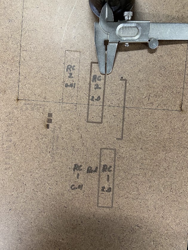
@Colin and @RalphU I can confirm that wider widths seem to raster correctly in RC2 and RC1 (see picture). I used a 2mm width and it looks to be about 2mm. However, when we think about the precision associated with the thin lines vs these thicker lines. Running a test of say 2.02mm and 2.00mm would be extremely hard to distinguish given the kerf.
The 0.01mm lines in both RC1 and RC2 are rastering, which means the print job is ending up with a line width that is wider than 0.0254mm. I was able to create a print driver which dumps the raw ILS 12.15 print job to a file and a print driver which pulls the raw output from the Lightburn Print function to a postscript file. The output from RC1 has a line width being specified for thin lines,
gsave simpInitG
[0.75 0 0 -0.75 0 792.000122]++
[1 0 0 1 48 48]++
csv 720 0 720 960 0 960 3 0 0 ml
cp ec np
233.919998 448.480011 233.919998 511.519989 486.079987 511.519989 486.079987 448.480011 4 233.919998 448.480011 ml
233.919998 448.480011 l cp 1 0 0 rgb 2 sj 0.16 sw s
crs
[1 0 0 1 48 48]--
showpage
grestore
%%Trailer
%%Pages: 1
%%EOF
but RC2 does not.
%%EndPageSetup
gsave simpInitG
[0.75 0 0 -0.75 0 792.000122]++
showpage
grestore
%%Trailer
%%Pages: 1
%%EOF
To help clarify how to read the output from RC1 for thin lines, The line width is set by this part:
0.16 sw
In most PS prologs, sw is a shorthand for setlinewidth, so it’s 0.16 in the current user-space units at the moment of stroking.
Because there is a scale transform right before ([0.75 0 0 -0.75 0 792.000122]++), that width gets scaled too. So the effective device-space linewidth is:
- 0.16 × 0.75 = 0.12 (in default PostScript points, that’s 0.12 pt)
- 0.12 pt = 0.12 / 72 in ≈ 0.00167 in (≈ 0.042 mm)
So it’s effectively getting a line width of 0.0420mm > 0.0254mm and ends up rastering.
What about RC1 and RC2 for wider lines? Let’s see. In this case, the print defines a geometric shape with an inner and outer edge and a distance between them in both RC1 and RC2 the outputs are the same:
gsave simpInitG
[0.75 0 0 -0.75 0 792.000122]++
[1 0 0 1 48 48]++
csv 720 0 720 960 0 960 3 0 0 ml
cp ec np
486.079987 444.720001 489.839996 448.480011
489.839996 511.519989 486.079987 515.279968 233.919998 515.279968 230.160004 511.519989
230.160004 448.480011 233.919998 444.720001 237.679993 452.240021 237.679993 507.759979
482.319977 507.759979 482.319977 452.240021 233.919998 452.240021 13 233.919998 444.720001 ml
1 0 0 rgb f
crs
[1 0 0 1 48 48]--
showpage
grestore
%%Trailer
%%Pages: 1
%%EOF
The edge/border thickness is the difference between outer and inner edges:
- Left thickness: 237.679993 − 230.160004 = 7.519989
- Right thickness: 489.839996 − 482.319977 = 7.520019
- Bottom thickness: 452.240021 − 444.720001 = 7.520020
- Top thickness: 515.279968 − 507.759979 = 7.519989
So it’s essentially ~7.52 units thick (in the current user space at that point).
Because there is a scale matrix [0.75 0 0 -0.75 ...], the effective thickness on the page is scaled by 0.75:
- 7.52 × 0.75 ≈ 5.64 points
- 5.64 pt = 5.64 / 72 in ≈ 0.0783 in ≈ 1.99 mm
That means that we’re sitting where we’re shooting for, within tolerance, at 1.99mm ~= 2mm.
It looks to me like, at some point, Lightburn is deciding, in the print job, that at some nominal width, it needs to not draw a box with an inner and outer edge, and instead just draw a box. However, in RC1, it also specifies a stroke width where in RC2 it does not. Without a stroke width set, it’s up to the print driver to interpret the line width and it doesn’t interpret it as thin enough. With the stroke width set in RC1, it’s processing an incorrect calculation and the stroke width isn’t coming out to the correct value.
I can run some more tests to try and figure out where that is happening, but I feel like this is a significant amount of detail which the dev team should be able to use to try and hunt this down. I say this in my experience running both large and small dev teams building a variety of applications.
Also it’s important to note that most of what I’ve done can be tested and vetted completely outside of having access to any sort of Universal laser. Certainly confirming that a 2mm line rasters as a 2mm line would need the laser itself, but the raw output from the Lightburn Print function shows a distinct difference between what it’s delivering for a wide line (identical in RC1 and RC2) and what it’s delivering for a hairline and the hairline value in RC1 and not setting any value in RC2. This isn’t a function of the print driver interpreting the data that LB sends, this is the output from LB itself from what I see.
Let me know what you all think and anything else I can do to provide details or feedback to help make the hairline width function work as intended. We’re very excited to see if we can get this to where we need it to be and again, thank you for everyone’s hard work on this. I and our whole community of makers here appreciates it greatly!!
Inkscape will also send everything to the Universal Laser Systems UCP as raster if you just use their print dialog. But, If you use an extension under export called Win32 Vector Print, it sends the data correctly to the UCP.
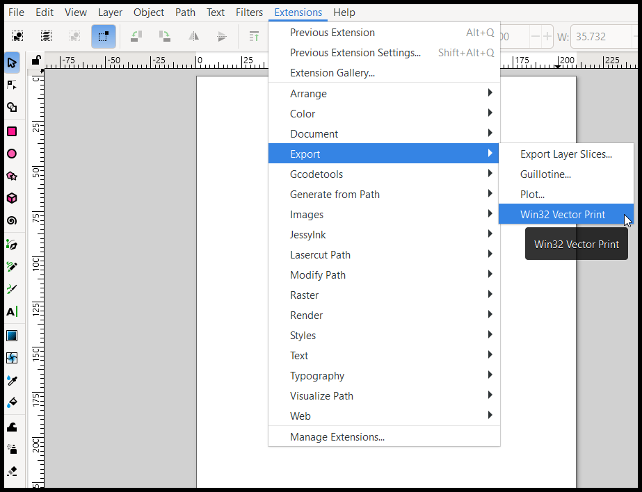
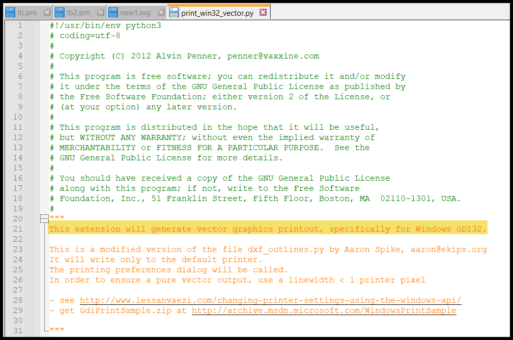
Here is the python script that Inkscape uses for printing to the Universal Laser Systems UCP
Location of Python script on a Windows computer is:
C:\Program Files\Inkscape\share\inkscape\extensions
I am using the latest version of Inkscape 1.4.2
From what I have found, in order for it to work correctly, LB would have to use the Windows GDI -Win32 app below. I am assuming that LB is not using this app for printing.
That’s interesting. In my experience with Inkscape and sending to the UCP, as long as the “Stroke Style” width is set to “hairline” it is interpreted as a vector cut by the UCP. I’ve not needed to use an extension to get Inkscape to work personally.
That doesn’t work for me on the latest Inkscape version. When I set the stroke width to hairline, and File>Print, it comes out raster in the UCP.
When I create a 2mm RGB red line in Inkscape, it comes out 2mm wide black raster in UCP.
When I create a rectangle that is RGB red and 0.0254mm and use the Win32 Vector Print extension, it comes out as vector red in the UCP.
I am pretty sure that most of the printing to UCP was developed in the late 90’s and up to late 2000’s. The updated version of UCP today doesn’t look much different than what they were using a LONG time ago, except the material database is much larger.
@Colin let me know what your thoughts are on my post from yesterday characterizing the outputs for the wide and thin lines, whenever you get a chance. I’d be interested to hear what the team thinks and if there’s anything additional we can do to help provide details needed to improve the functionality around the line width. Thanks again for all you do!
I’ve re-raised this internally for review because it’s outside my current technical expertise. Once I get a second opinion from our talented dev wizards, I’ll come back with next steps.
4 Likes