I have posted about this subject a couple of months ago and received good feedback from the forum. I tried many different tools and combinations thereof and have come to the following:
I am using KiCad to make the schematic and the PCB layout. I needed to enlarge the pads and widen the traces, cause otherwise the would be too little copper to solder components on to (Thruhole)
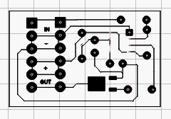
Export the PCB layout to an .svg file.
Open the svg file in Coreldraw and export to a .png file. If skipping Coreldraw or converting using e.g. PCBconverter the image resolution is not good enough, or the traces and pads look jagged.
Open the png file in windows paint and reverse the image and save as png again. This is because the laserengraver is used to burn away paint on the copper, so you the pads and traces to be white and the areas between them, black.
Now I can open the reverse-image png file in Lightburn and start burning off paint. I did many trial and errors to find good laser power (20%), speed, interval settings to get a satisfactory result.
Finally, wash the PCB board and etch it in ferrite chloride.
I have not yet been able to create a finely detailed PCB with narrow traces and smd footprints. I wish I could eliminate the step using Coreldraw, since it is a fairly costly license, and I have not found an alternative yet.
I haven’t made any pcb’s with my laser but, I have designed them for a cnc machine.
Why are you converting a svg it an image? That makes jaggie. You already have an svg which is so much easier to work with and doesn’t have jagged edges. I’ve been editing photos in Photoshop for 20 years or so. All that converting has to degrade the design.
I could all be done in Lightburn but, I prefer Affinity Designer to do svg editing. I find it easier to move nodes around. You can by using colors come up with as many layers as Lightburn has.
You could also use Adobe or Inkscape. For me Adobe is too expensive and Inkscape isn’t very intuitive.
opening the svg file in Lightburn will only show the centerline of traces and the outer curcumference of pads.
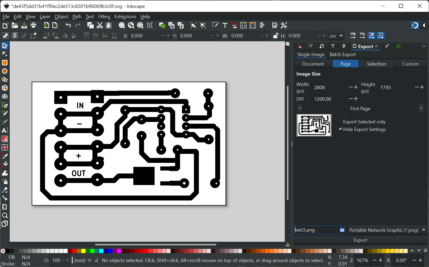
Using Inkscape to convert svg to png results in too low resolution image in lightburn. That is why I used Coreldraw.
but I can resize the iage in Lightburn without losing resolution, so I will use that going forward, I think. I’m just concerned if I can resize it with enough acuracy to be able to use it for smd.
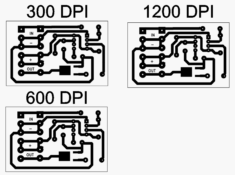
I’ve never seen this. I just tested this with a 100x100mm square at 300 DPI and 600 DPI and the imported sizes import at 100.33 mm square and 100.288 mm square respectively. What version of Inkscape are you using? And how are you doing the export?
Have you tried resolving the issue with SVG? I think that would be the best path forward if possible.
I am using Inkscape version 1.2, and doing a single image export to png,
I don’t how to fix opening svg in Lightburn. I has a similar issue with pdf files, where everything is vectorized,
I tried reversing the image in Lightburn using tools → adjust image. I get a new window where I can see the origianl image on the left and on the rigth I also see it and where I can Invert Display, but there isn’t a way to save it and use it for the burning, or at least I can’t find it. I could not find any ‘cut settings’ with an reverse image option.
You stated you’re only getting the centerline of the strokes. That’s because the line is being defined as a vector with a stroke. LightBurn doesn’t account for stroke so interprets the line as essentially infinitely thin. Does KiCad have the option to convert the stroke to path on output? If not, perhaps loading to Inkscape and then converting all objects and strokes to path, and then loading that into LightBurn would work.
I concur with @Somewhereinusa, if you can upload a sample SVG file and perhaps an image of what you’d like it to look like at the end some others can take a look.
I’m tagging on to this question as it seems to be related - importing SVGs exported from KiCad into LightBurn. If you think I should rather create a separate post for this, please let me know and I’ll do that.
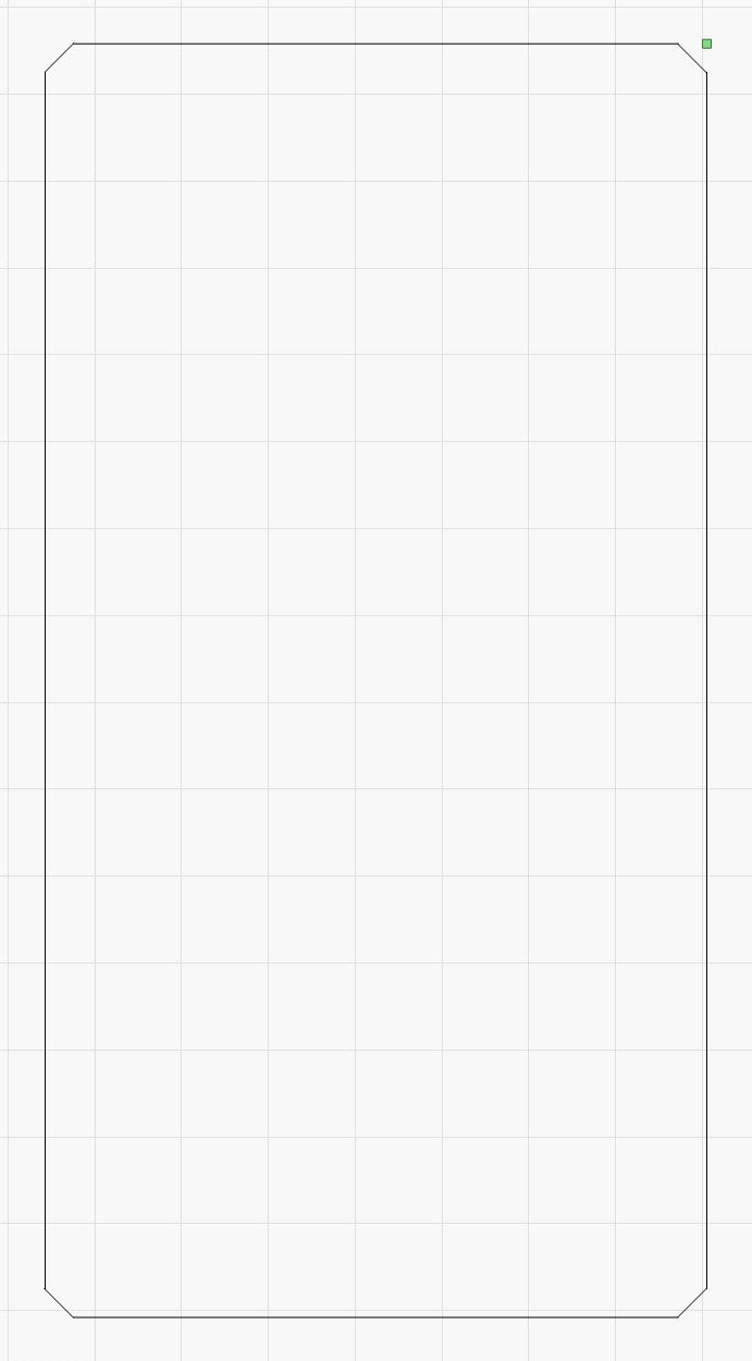
I often cut parts related to PCBs. As such I use the KiCad PCB design files as the source - I export the board outline and some other layers from KiCad into SVG and then import it into LightBurn. Unfortunately I need to use an intermediate step at the moment opening the file in Inkscape and exporting to DXF as LightBurn cannot correctly import the KiCad SVG files - specifically, the corner arcs are imported as “cut off corners”. Here are the relevant files:
I guess LightBurn doesn’t correctly support the SVG feature used by KiCad… Would it be possible to add support? It’s not too big of a deal as it only takes a minute to open the file in Inkscape and save it as DXF, but it would be nice not to have to do it
Seems this is a fundamentally different problem from original poster but possibly related in terms of how SVG creation is handled by KiCAD.
After looking at the file there’s a more fundamental problem in the way the SVG is generated. Looks like it’s not being created as a single closed shape but rather as a group of a series of aligned line segments.
A “better” fix than what you’re doing may be to:
Open KiCAD SVG file in Inkscape
Ungroup shape revealing the individual line segments
Join all line segments. Not sure if there’s a more elegant way to do this but using “Edit paths by node” tool, select all segments, then “Join selected nodes”
Resave as SVG
Import into LightBurn
This should now look correct and you can avoid the DXF route which is a lossy process.
If there’s a theme in this it’s that KiCAD seems to generate some really awful SVG files. Seems to be taking a purely superficial approach to placement of shapes without regard to correctness in design.
It would be possible to correct for this as an SVG but would take a considerable amount of manual correction. I see the attraction in converting to a bitmap in that case.
I took the SVG, opened in Inkscape, and can export to PNG with arbitrary DPI with no issue of resizing when imported into LightBurn.