Currently using A4988 drivers. Worth updating to TMC2209?

My home built Laser is running the MakerBase DLC32 V2.1 controller with A4988 drivers set to 1/16 steps. Would I see a noticeable improvement in smoothness by upgrading to the TMC2209 drivers & setting them to 1/32 or 1/64? I am seeing anomalies that might be getting generated by a lack of smoothness. If I read correctly, there are downsides to running at the more granular increments such as lower power being provided.

After checking & adjusting everything possible mechanically, both axis are extremely smooth when moved by hand.

Thoughts?

Thanks!

A few good pictures will help us see what you see.

With that in mind, though, it’s unlikely higher stepper resolution will make any difference. Assuming a typical 16 tooth pulley and 2 mm belt pitch, each motor step works out to 10 µm, far below the mechanical backlash / slack / stiction / whatever of the RepRap-grade hardware we all use.

Now, if you’ve got something exotic going on in your shop, we’d all love to see it! :grin:

Run this test pattern for a quick check of the machine’s mechanical integrity:

GrundTest.lbrn2

Scale it uniformly to fit the platform and run it as fast as the machine will go in Line mode with optimizations turned off and power set to mark a sheet of cardboard. Any differences from the design will be informative.

1 Like

I used a piece of poster board to max out the size (660mm x 505mm). After I posted last night, my mind was still working on laser projects and couldn’t sleep, so I headed back down to the laser and went over all of the wheel and belt adjustments. The X-axis belt was a little on the tight side. The Y-axis belts were good. I started from scratch on the wheel eccentric nuts and adjusted them. My method is to completely loosen them, then gradually tighten them until the axis moves when I rotate the wheel with a thumb and index finger. I figure at that point, there is no play in the wheel and will hold everything steady with no slop.

This morning, I ran another material test on the pine wood I’ll be engraving a large project on. The vertical banding I was seeing was diminished after the adjustments last night, but it’s still there. I also wonder if there’s a difference in the smoothness between the Nema motors made by different manufacturers. Or are there any adjustments I can make in Lightburn? Beyond that, I can’t of anything else I could change to completely eliminate the vertical banding.

The new project will be a large logo (678mm x 550mm) and I’m trying my best to hit the nail on the head since it will take several hours to engrave. With this type of engraving, I like to engrave deep into the material to really expose the grain. This is what I did when I finally took the time to make something for myself, the Chicago plaque. You can easily feel the grain in the large “C”.

Thanks for any advice that can help!

I hate it when that happens … :grin:

It looks good (and way better than some), although these patterns suggest the laser power is falling more than it should just before the end of each vector:

Assuming it’s a GRBL controller, then increasing the acceleration on both axes should help:

Repeatedly running that test pattern at high speeds should provide enough motion changes to show when the acceleration gets too high, by the simple expedient of having a motor stall when it can’t provide enough torque. Just drop the acceleration by a few tens of percent and it should be all good again.

It’s apparently possible to manufacture belt drive pulleys juuust slightly out of round or bore their shaft holes juuust a little off-kilter, thus modulating what should be smooth linear motion juuust enough to make a difference.

Bonus: idler rollers can be out of round, too.

Measure the “wavelength” of the banding, divide by π, find every pulley or idler of that diameter, and give them a close inspection.

That’s nice work!

TMC2209’s will be quieter and give slightly more power. It would definitely improve smoothness. Also, can increase steps/mm. I come from the 3d printing community. Even when I started, A4988’s were on the way out the door with better driver’s being 8825’s and the tmc2130’s. Now, TMC2209 and TMC5160’s are prefered. TMC5160’s are used with 48v system’s. None of the other’s will handle 48v.

Visually, there’s no fluxuation in the pulleys. The issue is happening more frequently than one revolution of either the stepper pulley or the pulley on the adjuster at the other end. I wonder how smoothly the contact of the belt to the teeth of the pulley is. Unable to tell with the pulley on the stepper because of the cogging of the motor.

I’ll experiment with acceleration this evening…

I don’t think so. I never noticed any difference in any of those drivers. I also came from the 3D printing community where I upgraded all my printers to TMC (mainly because of the noise), but for lasers, there is no real gain. If you have two options, I’d choose the TMC, but if you already have a system running A4998, I doubt you will see a difference in results. The mechanics are not precise enough to profit from the minimal gain in stepping smoothness.

Aaaahhh!

Here’s a nightmare scenario for you:

So it’s possible the belts and pulleys don’t match, even though their labels say they should. Other than inspecting the pulley and belt teeth next to each other, I don’t know how you’d check for that.

FWIW, I got a just slightly out of spec leadscrew that drove me nuts for a while:

So bad parts are definitely a thing.

Do you have a linear rail on the x-axis? If not, this will really help and be a game changer.

2040 rail with stepper at the left end & adjustable pulley at the right end with a belt that ends on either side of the laser head.

Then maybe the slider / ball gears of the linear rail is broken / needs to be lubricated. There is a quite regular pattern in the results, that looks like a mechanical effect.

I replaced all of the POM wheels (x and y axis} a week ago while I had it disassembled. The issue was the same before the replacement.

The thought just hit me to loosen the two grub screws on the x-axis stepper pulley so that the stepper motor would not spin as I moved the laser head back & forth. It was silky smooth as I moved the head at different speeds. Based on this, the issue isn’t being generated by the interaction between the pulley & belt.

Just trying to eliminate as many possibilities as possible…

This is the stepper motor on the x-axis of my laser. It came with the Two Trees TTS-55 laser unit I started with. I ported the hardware to my home built laser. I have no idea where this stepper falls on the quality spectrum. I’ve been curious from the beginning if the steppers themselves are generating harmonics what are being translated to the engraved images.

What are some of the highly recommended stepper motors available?

Usongshine 17hs2408sd

There are two of these (usongshine 17hs3401sd) on the Y-Axis:

The Two Trees 5.5w laser module I upgraded from weighs a LOT less than the Laser Tree K60, which weighs in at 2.78lbs. Just to throw it out there, am I needing to upgrade my steppers to something stronger to accommodate the larger mass the mechanics need to move around at higher speeds?

Just a thought…

Ah, then I misunderstood. You don’t use a linear rail. A few things:

  • you will never have a perfect straight x-axis when using wheels. This can’t be perfect because every wheel introduces slight variances in movement.
  • prefer polycarbonate wheels over POM wheels. They are stiffer. POM wheels are usually the worst option.
  • In this picture, the laser head is sitting way too low. Try to get it as high as possible, so the movement effect of the slider is minimized. The deeper you mount it, the stronger the wiggling-effect will be.
  • Those mechanics are not made to handle such heavy heads. My bottom line is: get a linear rail for the x-axis, then most issues will be gone. For such a head, maybe MGN15 is better than common MGN12.
  • The stepper motor is fine. Of course, using such heavy heads, you can’t go high speed, I’d guess that around 4000-6000 is the maximum here. You don’t use such heads for detailed engravings anyway, those heads are mode for cutting, so low speeds are expected and should not pose a major issue.

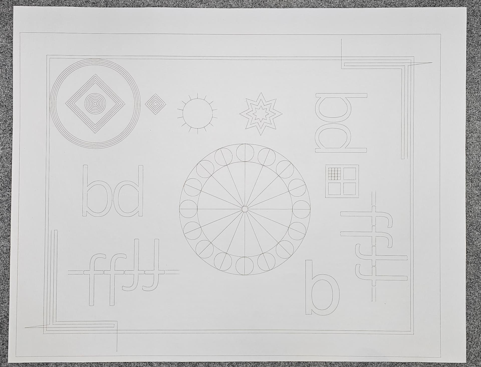
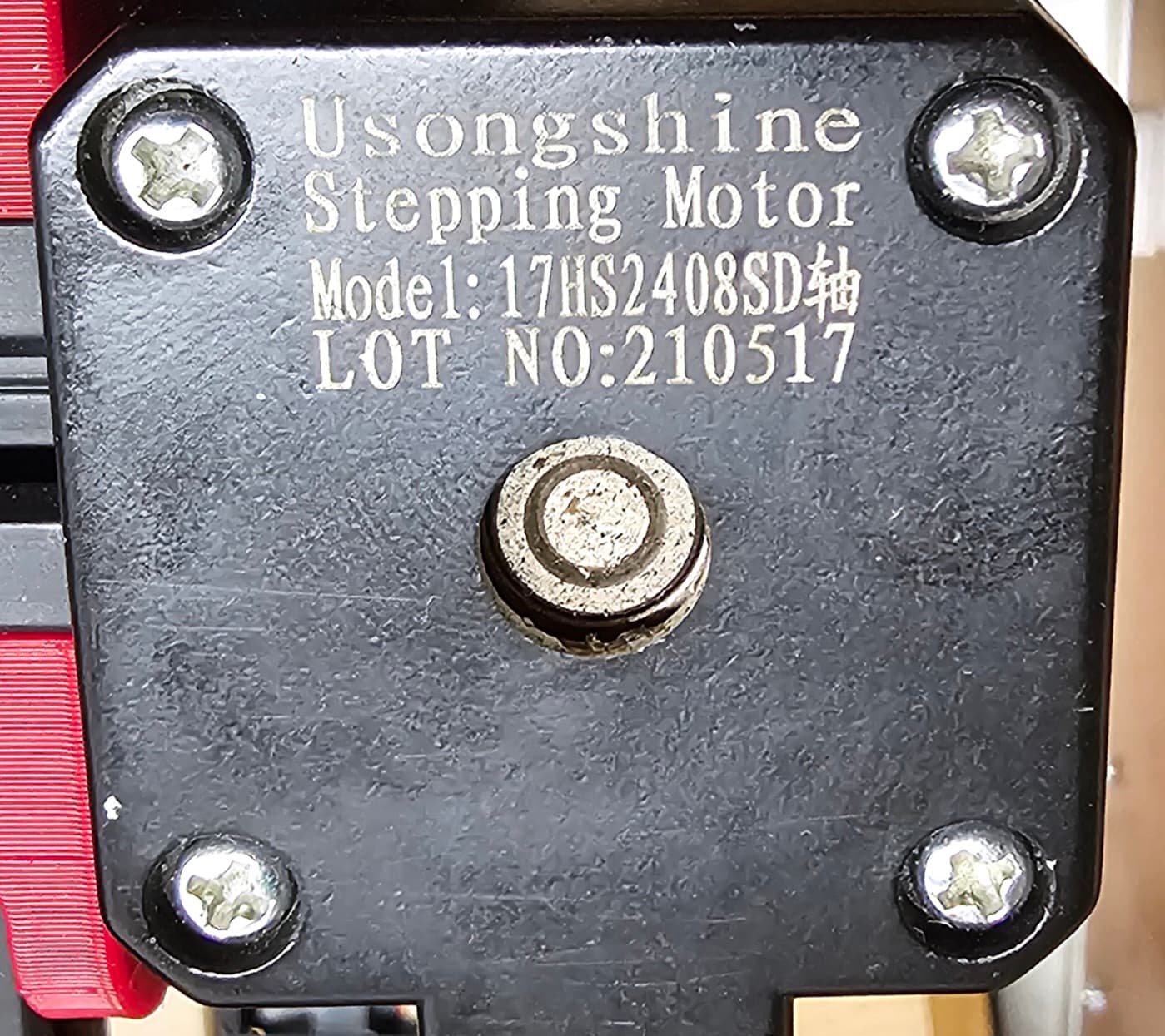
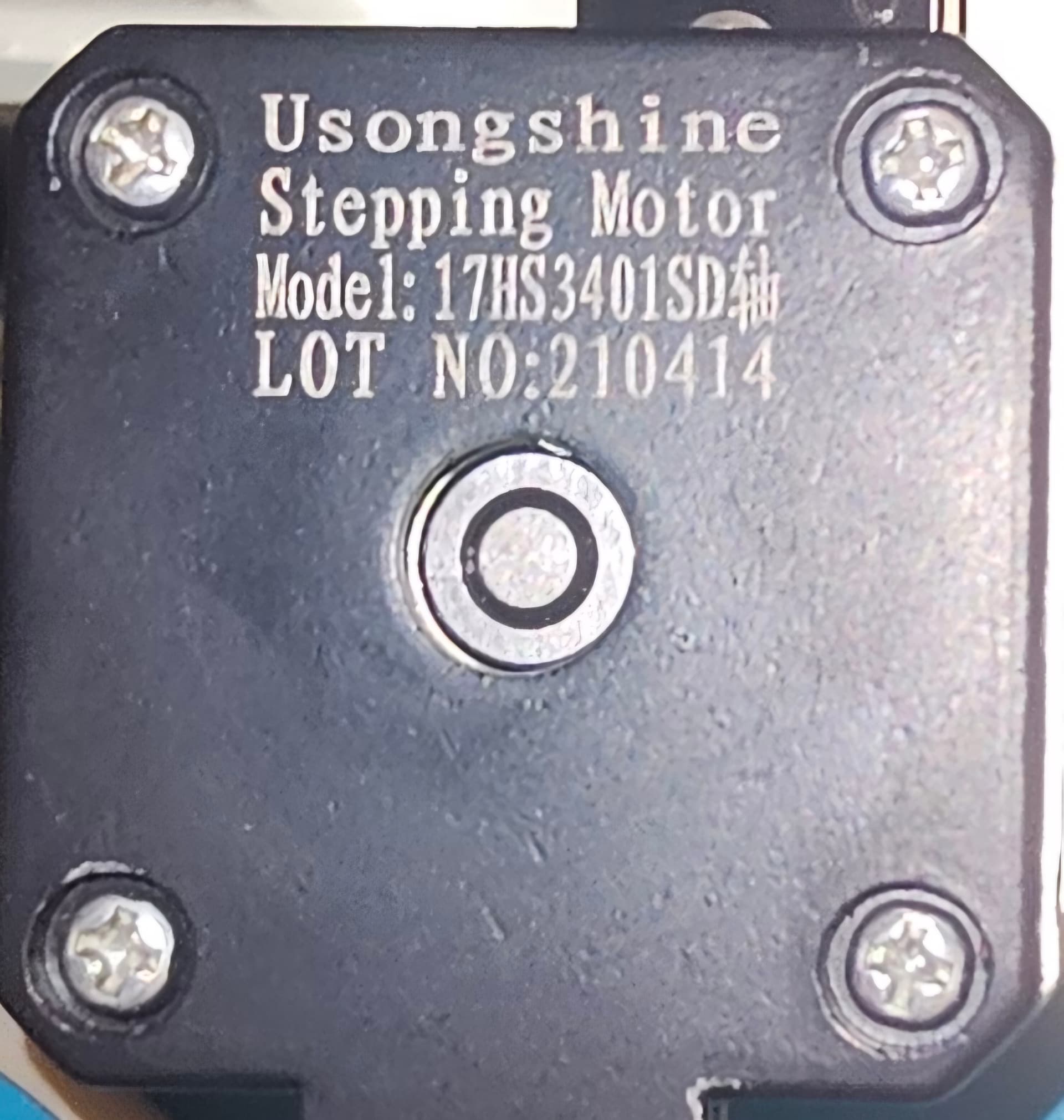
What I was seeing isn’t matching up with the rotation of a v-slot wheel or stepper pulley. The frequency is higher and very consistent. Since adjusting the belt tensions and POM wheel eccentric nuts, it’s difficult to see the banding at all.

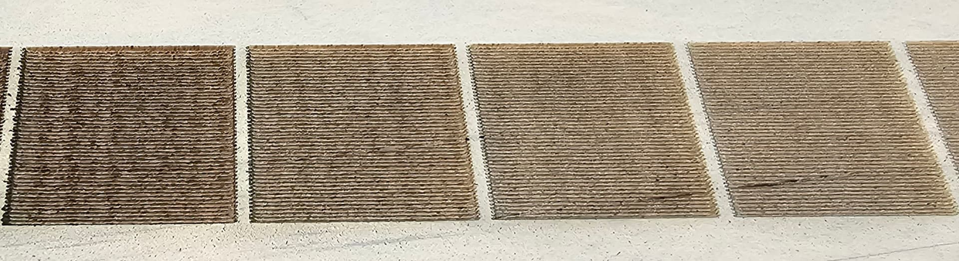
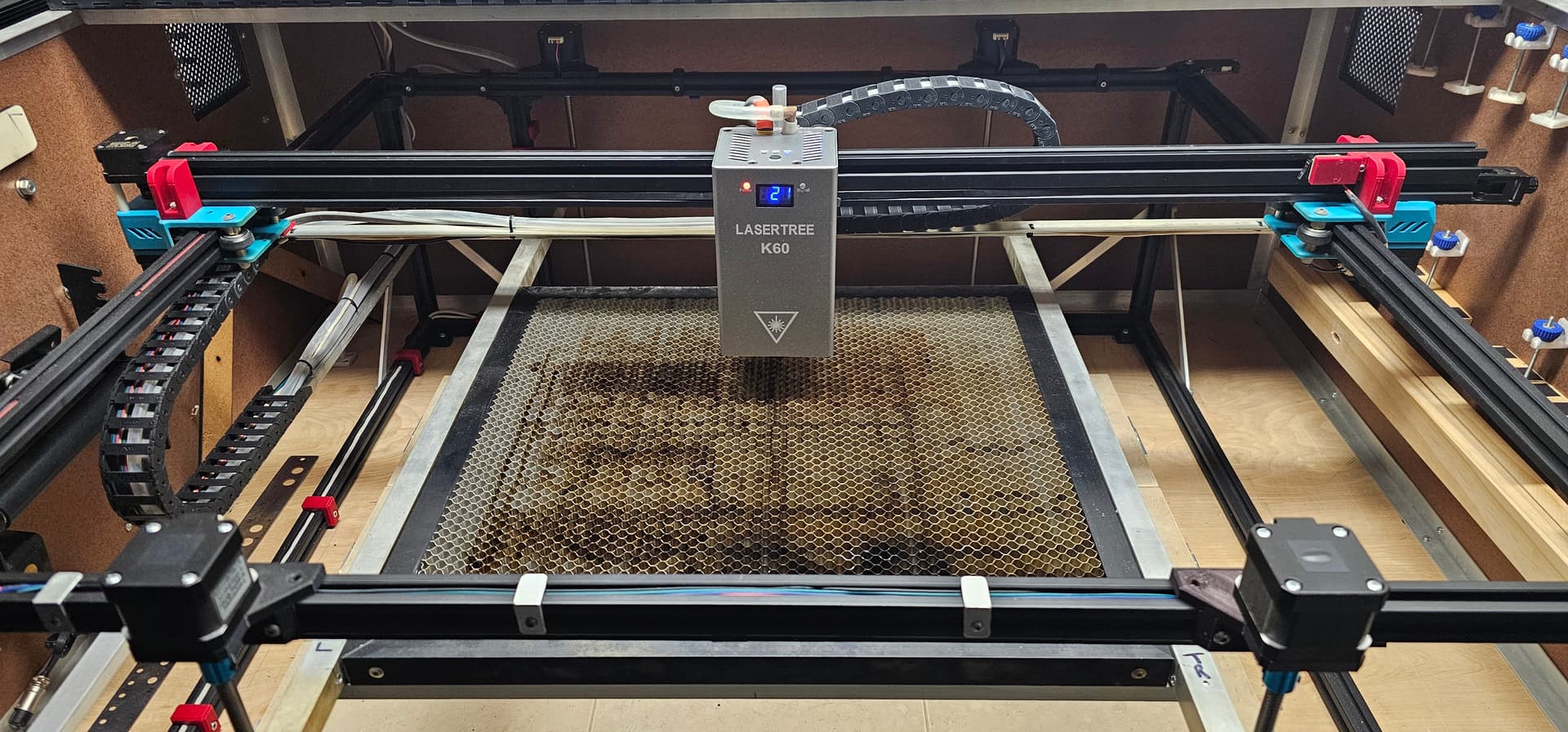
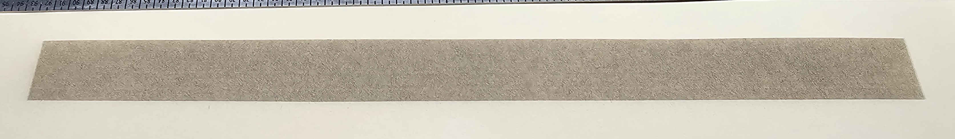
This a block 20mm high and 250mm wide, with the K60 set to 20w and running at 9000 mm/min, 50% power, and an interval of 0.200 mm. It looks extremely clean. Based on the spacing of the bands, I was suspecting either harmonics from the X stepper motor or something produced by the belt. I was running the belt too tight and once loosened, the banding was pretty much gone.

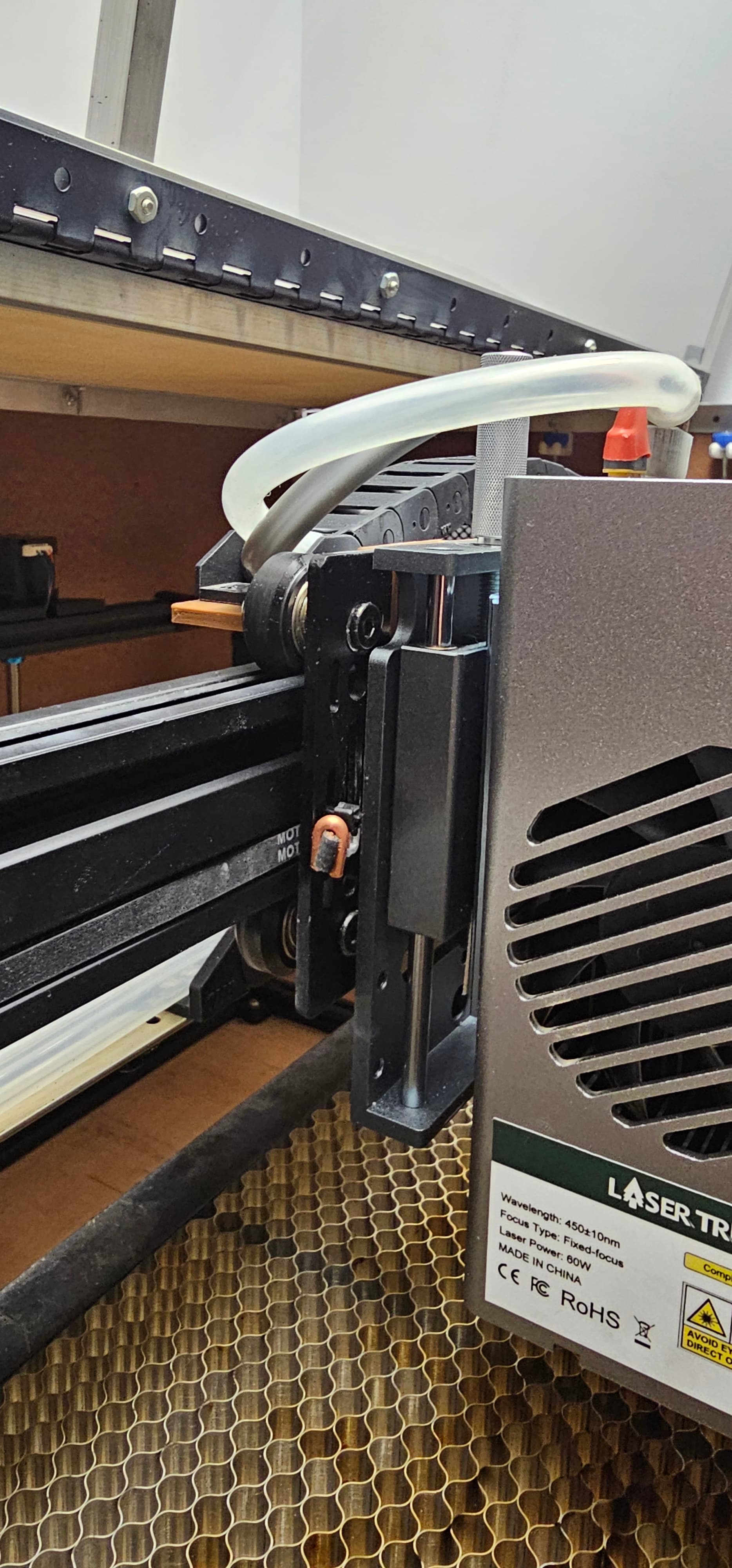
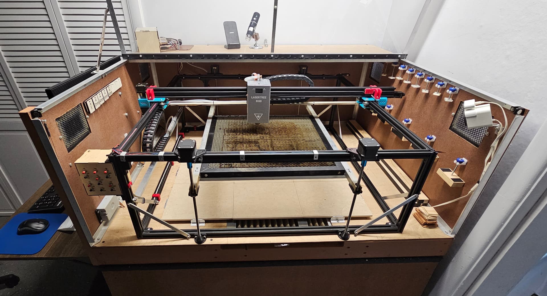
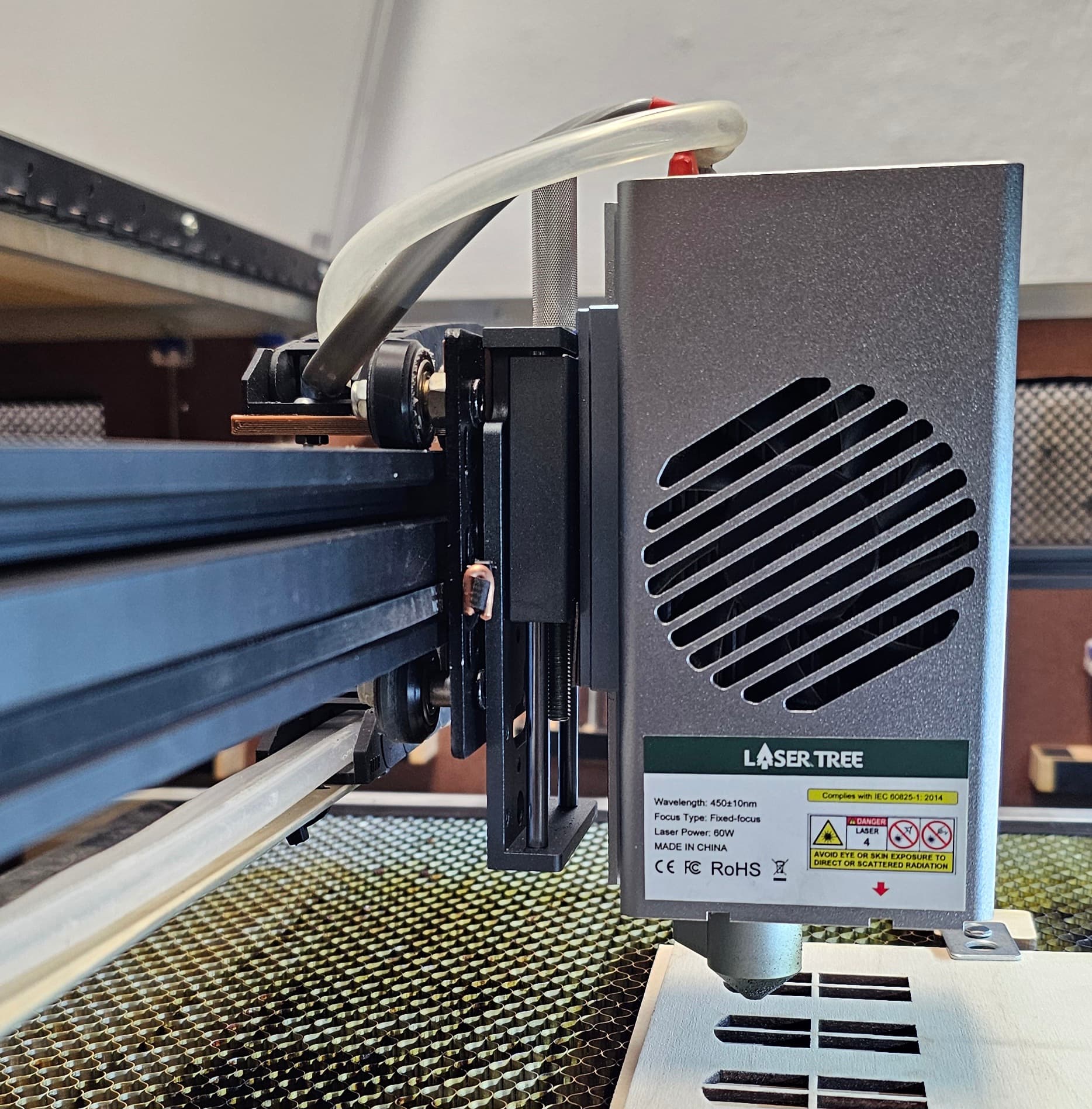
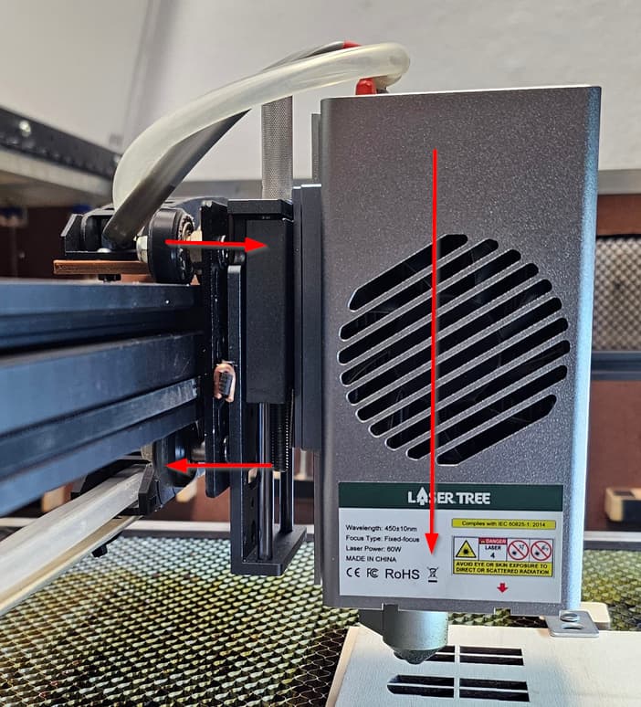
My old 5.5w laser head weighs 220g/7.76oz. The K60 weighs 1263g/44.55 oz. When I built the new laser frame two years ago, I used a 2020 v-slot rail, which was fine for the old, light weight laser head. As soon as I hung the K60 on it, I immediately knew that it needed something stiffer. I swapped out the 2020 rail for a 2040, and designed and 3D printed the thick red brackets at each end of the gantry. They’re bolted to the outer rail wheel axels. It’s as rock solid as I can make it. From red bracket to red bracket, the gantry is 36" wide, and I’d be afraid of a linear rail twisting over such a long length with the heavy K60 hanging on it.

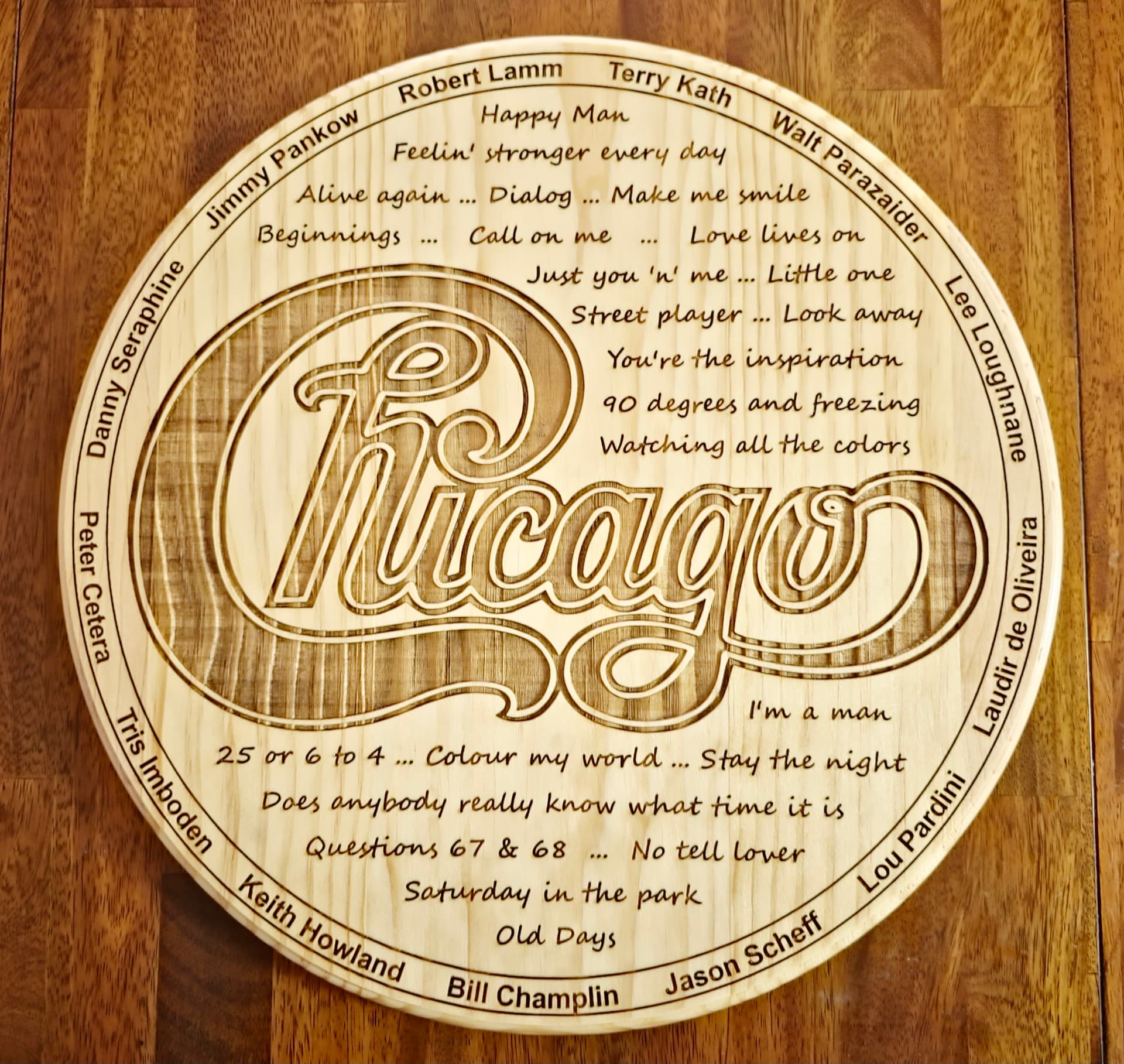
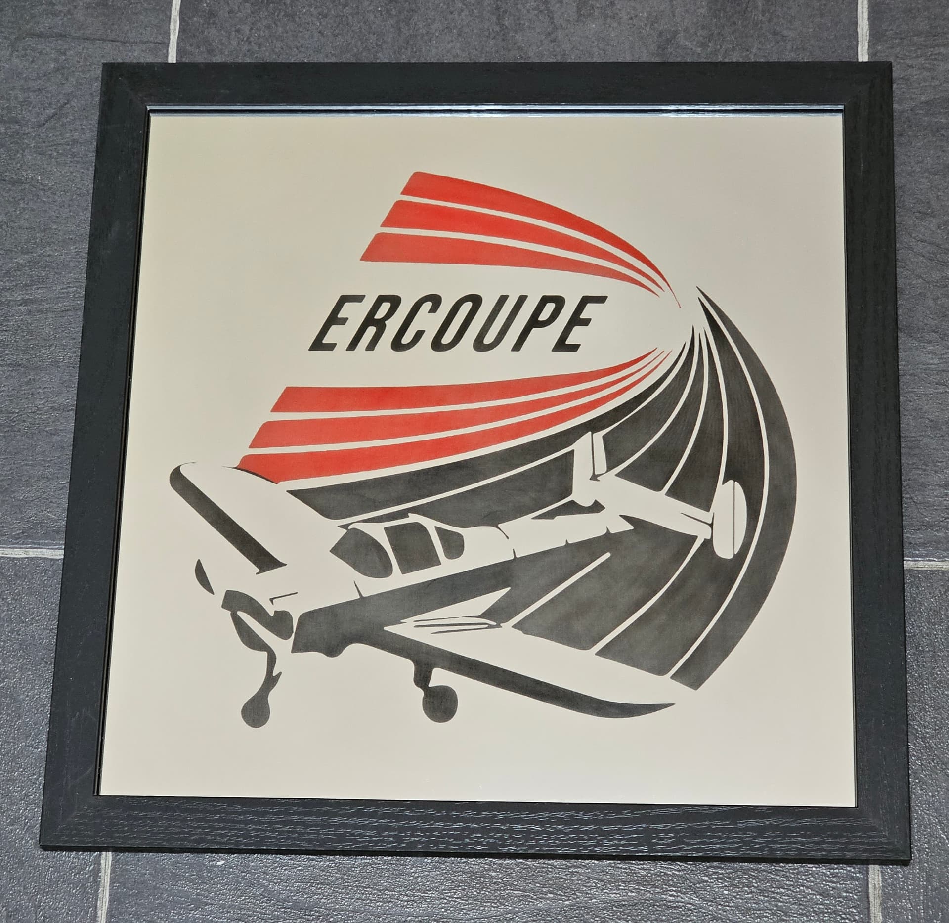
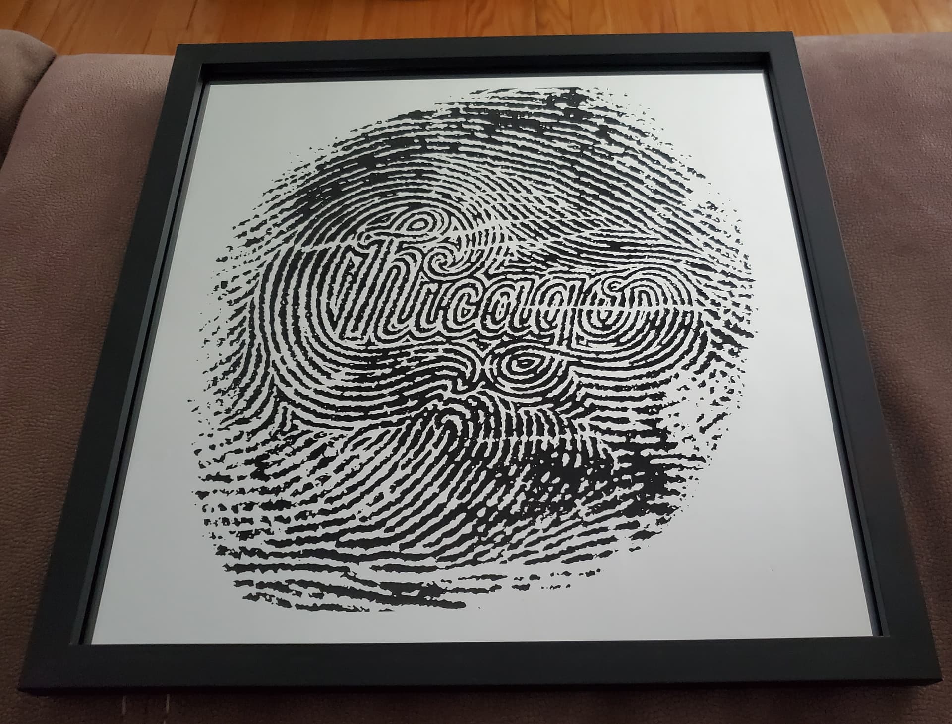
At a minimum, I’m going to replace the POM wheels with polycarbonate and stop there for now. I can dump more money into it but I don’t feel I’ll get enough gain to justify the cost. This is just a hobby for me, not a money maker, so I have to keep costs under control. Maybe in a couple of years, I’ll build a new laser and go CO2. For now, I’m having a blast making things out of wood, slate, chipboard, etc. I even discovered that I can laser mirrors by laying them facedown, turning the power way down, and the laser removes the silver reflective coating from the back of the mirror, then paint the back with different colors. They look really awesome!

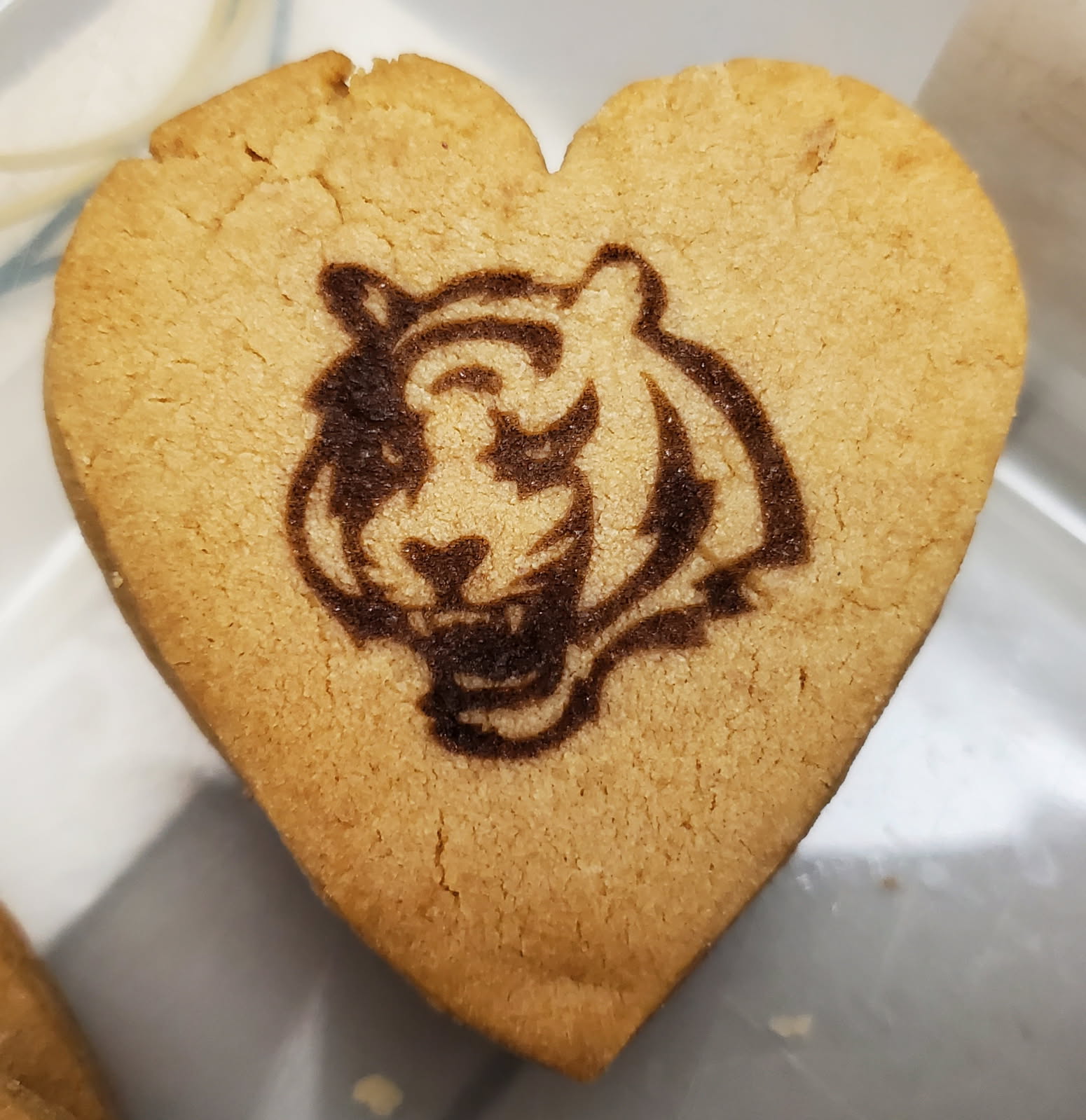
I even got really creative and engraved a batch of peanut butter cookies for a Bengals party!

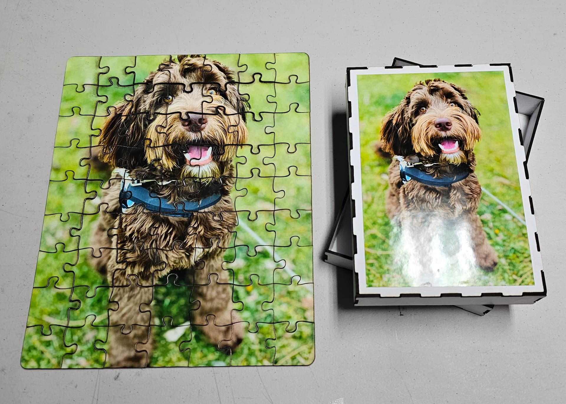
Puzzles using chipboard make awesome gifts too!

I want to thank everyone for all of the input I’ve received. Like any hobby, there is so much to discover.

2 Likes

The laser is typically adjusted to the top which puts it pretty much centered up/down on the 2040 rail.

That looks ok height-wise, but the center of mass is extremely far from the rail. I’d either put a counterweight on the other side of the rail or use a linear rail. The wheels are not made to handle strong forces perpendicular to the moving direction.

The current setup is extremely rigid. I have to push pretty hard to get the head to move at all. I don’t have the funds to experiment swapping to a linear ratio when there’s no guarantee it will improve anything. The issue I was experiencing is gone, so I’m going to run with it as it is.

Thanks for the info!