Hi all,
Just completed a DIY build. Looking to fine tune the system. Using a RDC6445G, CR-50W Laser Tube, MYJG-50W Powr Supply.
Should i be able to cut 3mm acrylic? Tried at 10mm/s and 70% and did not cut thru.
Hi all,
Just completed a DIY build. Looking to fine tune the system. Using a RDC6445G, CR-50W Laser Tube, MYJG-50W Powr Supply.
Should i be able to cut 3mm acrylic? Tried at 10mm/s and 70% and did not cut thru.
Some additional details would help, I have a 50W and cut 6mm with ease at 5mm/sec @95% power. Note that I have adjusted my laser output power with a resistor so that 100% is my max safe current for the tube. Before adding the resistor 55% was my max safe current power level.
At 70% you may be overdriving your laser, have you checked what the max current is for your tube?
Have you done a full focus alignment?
7mm/s @ 75% for 4mm - 3mm/s @ 80% for 6.33 - 50 watt (880mm) ‘China Blue’ ![]()
What kind of a ‘spot’ are you making? How confident are you on it’s alignment?
![]()
Yes, you should be able to easily cut 3mm acrylic.
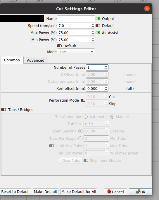
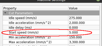
What is your “min” power setting?
At speeds of 10mm/sec and below your ruida controller will default to that min setting so if it’s set very low you won’t get anything. Try setting min to same as max to start with. Or set your speed to 10.5 instead of 10…
Very confident in alignment. Used Co2 Laser Alignment Tool For "PERFECT" lens head & mirror alignment Zn – American Photonics
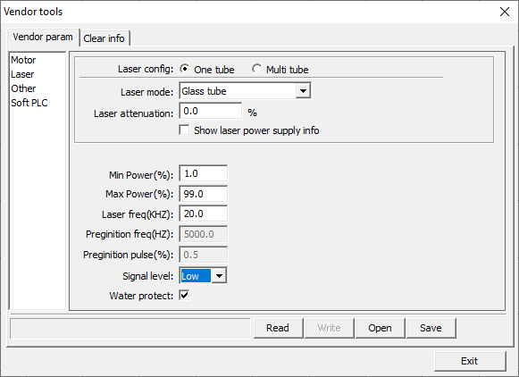
Max current for tube is 19mA, using digital meter to protect against going over.
focus is 5mm from tip.
Should i set min at 15?
thank you both. I didn’t know what to expect. I have seen guys with 50w zipping thru cuts but did not know the speed.
Regards,
Change your max and mins on the cut layer. These are min max for the machine. Unless you know what you’re doing, might want to stay out of the vendor settings. While you’re there make a backup of your machines settings.
Roger that, thanks Jack. Yup, i keep making backups after any changes.
Will results tonight when give it try.
I speak from experience, i am an IT Director. Backups can save your job, lol.
btw, can you explain the min power setting?
When the laser head is going to change direction the Ruida hardware will lower the pwm to adjust for speed change that must occur. When the head is going slow, the Ruida adjusts relative to the speed, but at some low speed point, it goes to the minimum. Many state it’s below 10mm/s, but I don’t know.
Here’s the docs from LightBurn.
Most people in the cut mode set them the same. You can tweak them. I cut a humming bird and lowered the min a few percent to avoid some burning in the small tight spots. It’s also real easy to get an incomplete cut 

10mm/sec appears to be the default most of the time. But it’s changeable in the machine settings if you want.
Is that what that does?
Mine is also set at 10.
I’ve only change the machine size and the X axes acceleration parameters. Well I have the door protect off …
Hey thank you both, i have a lot of data to test out tonight. I really appreciate it!
Will keep you all up to date on my progress.
Have you done the ramp tests and all that to be confident in your system?
Suspicious of your setup procedure, I don’t use that one, it feels backwards to me.
Good luck…
Thanks Jack,
The first thing i did was to align the laser, using the red dot from AP, I have the laser hitting my third mirrow dead center.
Next i did a ramp test starting from 3m, distance about 12inches.
Then i ran a 100mm distance checks on both X and y.
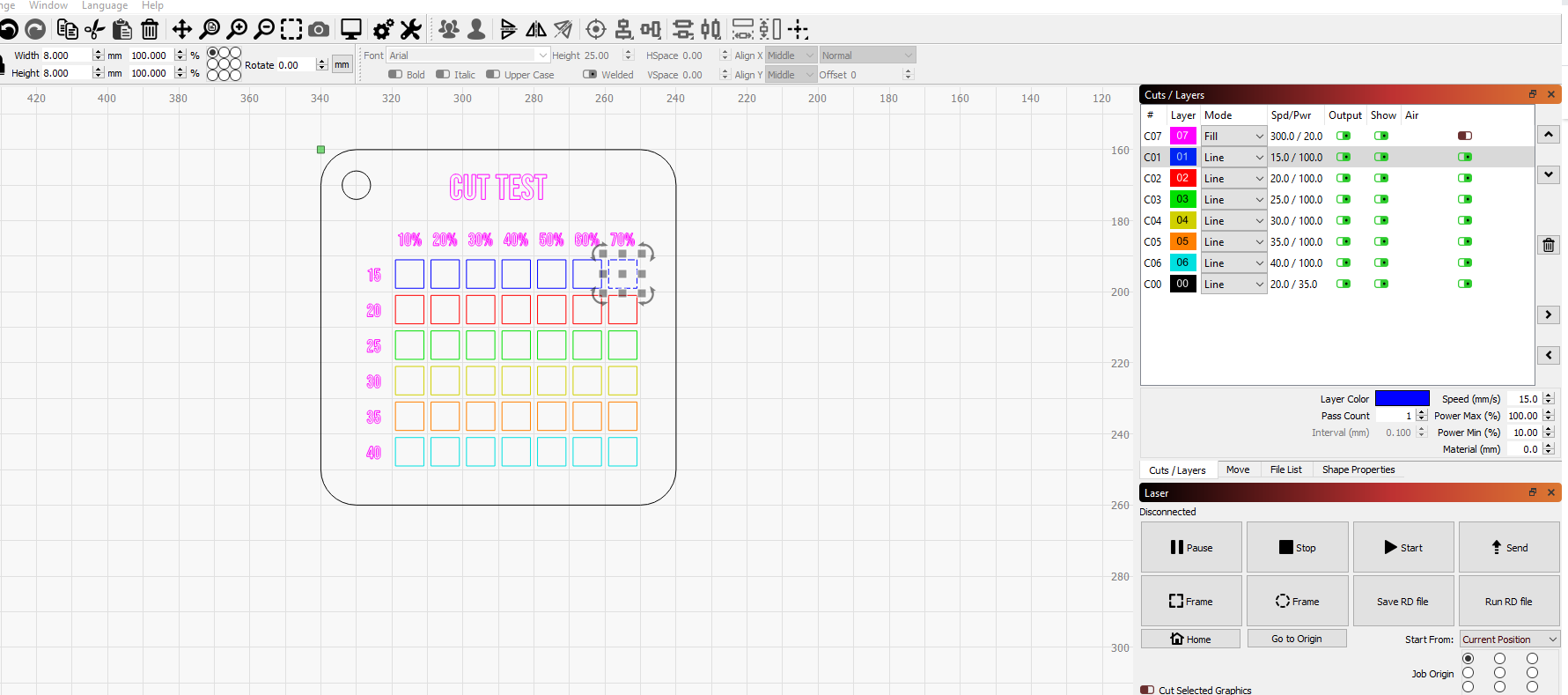
ran cut pattern, such as this one and noticed nothing was cutting.
And here I am now.
Am I missing something?
Thanks
Bob
Yep. At or below that speed the controller defaults to the “Min” setting for that cut layer. And it screws up a lot of people because they don’t realize that and their min setting is 0 and no matter how slow they go it just won’t cut…
You need that accuracy in the Z axes also. My original mirror on the head was 1.5mm offset from center.
Might take the lens off and pulse it on a sheet of paper on the table and see where it’s hitting and what it looks like.
Was there some kind of result?
Might explain what you mean here.
![]()
Sure, i checked Z axis by measuring distance between laser tip and bed at all four corners. All within 1mm.
Ramp test showed that the best distance between tip and material was 5mm. Got a really fine line at that location.
As for distance test. Ran this, then measured and entered results in calibration in LB.
This is NOT what I mean. We are talking beam path. Going into mirror 3. We are trying to figure out where it’s going from there.
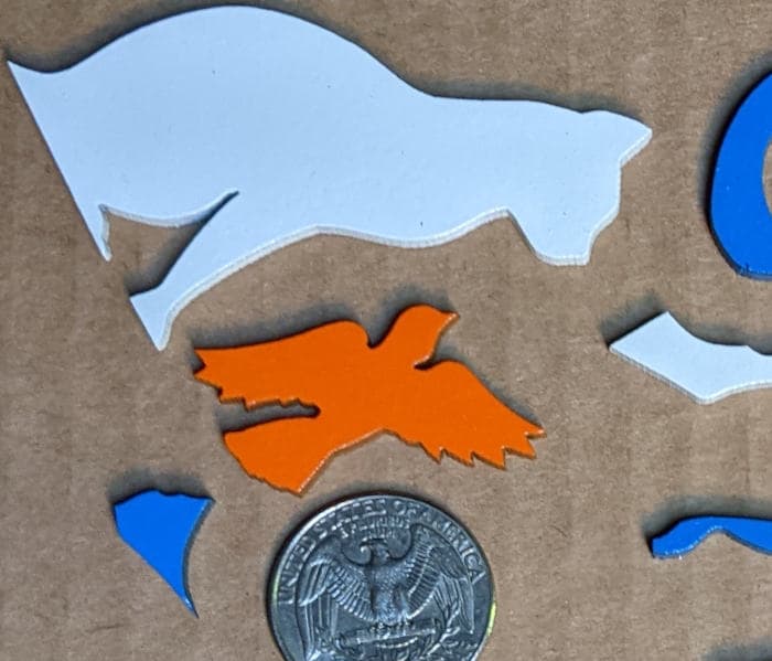
I like a pretty good difference between max & min when cutting a lot of stuff. Like 3mm plywood I typically use 65% max which is nearly full power at 24mA and around 22-24% for min, around 8mA.
Too much min power tends to incinerate small detail and round off little corners in a lot of stuff.
These little puzzle pieces were cut with 65%/22% and with to much min power those little bird feathers and other small detail just gets blown away.
For testing for appropriate min power on a material I usuually cut out little stars, maybe an inch high and set a minimum power that just barely (but reliably) cuts them out. If the tips char and round off, min power is too high. If they don’t quite cut through then min is too low. If the straight sides don’t cut then max power is too low or speed too high.
Not familiar with that test. Can you send me info on how to perform the test/calibration?