Where to start? OS is Windows 7 Pro , Om2-15
I bought my laser in May 0f 2021. Last night in the middle of a burn,
both my X & Y stepper motors started jerking back and forth real hard
while not going anywhere. After about 2 seconds, (at the most) the laser
shut down. Just as if you pulled the power plug. So I unplugged the
power supply and the USB cable and left it alone.
Now on to tonight. I checked movement in both X and Y motors buy
gently pushing the motors back and forth and left and right. No rough
spots or drag felt. Belt tension is good and tracks and rollers are clean.
Now I plug in power and the USB cable. I push and hold the power
switch for its normal 3 second start up. Mounted on the Ortur PCB right
above the reset/power switches are two little leds, one red and the other
blue. When I push the power switch, the red light flashes 3 times and
goes out for one second and then both lights come on and the laser goes
home and all is well. NOT NOW !!! I have to hold the power switch
for a good 8 to 10 seconds before the red light comes on and starts flashing.
And then nothing else happens at all. It’s not ALIVE anymore !!
Does anyone have any wild guess as to what happened?
I am still a nubeeeeeee !!! at this stuff. I bought my laser, (ORM-7w) in first week of May, 2021.
Had so much fun that I ordered my second laser at the end of the the third week of May. I have been
running “BOTH” of my lasers at the same time for 6 to 7 months now. And I am burning wood coasters on my Bl, (baby laser, 7W) right now while sitting here typing. So it’s not Windows. I am thinking what you said about hardware problems, I think your right. Also I couldn’t find anything on lights in the manual .
I started drafting a letter to Ortur last night. I think I have restarted it 3 times now. I have a new friend at Ortur now. This 15W locked up and “BROKE” the back board that X drive motor is mounted to. Not mention that before the back board broke, the bearings in the laser fan went bad. So Ortur sent me : one new back board, one front board that the laser mounts to, one new fan and they also threw in a power board to mount on top of the fan and they wasted no time in shipping me the parts. Ortur did me right !!
Anyway we will see what they have to say and go from there. I’ll let know on updates.
Randy
The backboard braking happened in May 2021. I bet I took a hundred pics as I took it apart. Found the problem, factory installed spacers not only backwards but also on the wrong side of the framework.
Ortur treated me right I sent them a detailed 5 page report along with nine well picked photos and in about 12 hours I got a response saying my new free replacements were on the way. And about 30 minutes I got a note blasted off to Ortur. If you ever have a problem with Ortur products, send a note to:
ariel@ortur3dprinters.com
This man will take care of you and waste no time. But watch out for “Mina” at Ortur, she trys her best to get you for 30 to 40 bucks for expedited shipping on factory damaged parts. I put a post on here about that and someone in the right place must have it because about 10 hrs. making the post, I got an e-mail from her saying that parts were being shipped expedited free of cost. I guess I got lucky. Well, thats all for now.
randy
Check to see that the plug in the stepper motors is secure. I had to zip tie mine onto the motor because they kept coming out. No lock to secure it on mine. Caused my stepper motors to act erratically. But it didn’t affect the laser, so might not be it.
hello Leo: Well its 4:45 am. here at home right now. I just finished testing my 15w. (aka 4.6w ) I have brought LIFE back to my boy again. ita alive, its alive!! I was right, it was the PCB of Orturs. I found the problem, resoldered the connection and was off to the races. You were right on the motor thing, in a way.
Where the 8 pin female plug plugs into the PCB, (motor control cable), I found a broken soldered connection around one of pins on the PCB. I resoldered the pin, every thing looked good so I put it back together and it works. Back in the late 80s and early 90s I worked for the DOD. I taught electronics and what we call HI-Rel soldering. So I had a good idea as where to start looking for problems. Anyway I’m a happy camper again.
Randy Cline
That’s great news. Glad I was able to push you into the right direction. Mine was at first start up. I was sooo disappointed that I got a dud. But it was simple enough that I just pushed the plug into the motor farther and away it went. Haven’t had issues other than that plug coming out once or twice. But then I strapped it in with a zip tie and no more issues.
Happy lasering!
Dont imagine you had pictures of this?
Were your connectors cable tied?
Hello Gil: NO, My wife was out of town with our camera. She is back now. If you like to see what I did,
I’ll be glad to pull 2 screws and 4 nuts and snap a few photos for you. Won’t take 4 minutes to pull apart.
Would you like me to post them here or would you like me to send them to company e-mail?
I use to teach electronics and what we call “HI-REL Soldering” for the DOD, (Depot. of Defense). So as soon as I looked at the back side of the PCB, I knew that the operator had the solder temp on the wave soldering machine turned up to high, that started to crystalizing the solder and showed signs of heat stress causing fracture cracks. Machine vibration did the rest.
Randy
I’m curious about this as well if you could share pictures here. I’m trying to imagine how this could have happened even with a brittle solder joint. I don’t see really any serious stress point where the mb would be exposed to a lot of force given the strain reliefs in place.
How many hours would you estimate you had on that unit? Have you examined the other unit to see any signs of wear and tear?
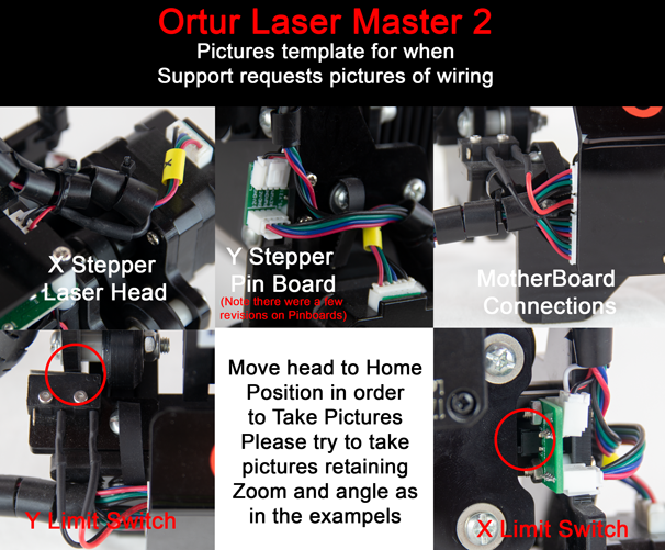
If you could replicate this angles/zoom levels and post that would help, your machine might have slightly different versions of cables but the locations are the thing that matters the most
Hello Gil: (and you also PY) :
When my 15w trashed the other day, I pulled my 7 w off its framework and mounted it the 15w
framework and then put the 15 on the 7. I did that to see if the 7w would power up, no luck. So I took a photo of the 7w eight pin plug plugged into the 15w PCB for you. I took a photo of the back of PCB showing where I repaired it. There is still a little flux on the two soldered joints. (far right side) My eyes are to old to see those tiny connections and just get to one of them, no way. So I desoldered and resoldered two joints. When you look at the PCB photo, on the right side, you will see the 8 pin plug from the backside. I fixed the two pins to very right. Looking at the photo of the face of the PCB with the cover on it, look at the bottom of the 8 pin plug, there is a red wire, then a blue one, that blue wire plugs onto the pin of the PCB that trashed out.
PY: Bear with me, to see if I get this right. When you say, “given the strain reliefs are in place”,
I think that you are talking about securing the wiring harness/cables with zip ties. Your wires flip flopping back and forth would be applied force to the board. I’m talking about vibration stress. Vibration caused by the two stepper motors humming their little hearts out. That vibration causes the bad pin to shake back and forth and all around town on a Sat. night, which causes the fractures to enlarge to the point of breaking. If you would like to see vibration stress with you own eyes, get a small clear shot glass and fill it about half full of water. Start your rig to burning a project and set the glass of water on front cross rail a couple of inches to the side of the cover plate / PCB. Wait a minute or two and you start seeing waves in the water caused the vibrating motors. That is vibration stress.
One more thing. The Hours: May of 2021 - back board jammed up and broke after 20 hours.
Today total hours, (15W) are around 650.
Today total hours, (7W) are around 1400 ( 7W is 3 weeks older than 15W)
to this day the 7W has never missed a beat.
Gill: I found another problem with this 15w frame & motors. I made a 12/15 second video so
you could see for your self. I have checked “EVERY” thing ! Compared everything to the 7 w. frame. I mean every nut, washer, bolt, spacers ID/OD/L. Rollers and the mounting boards. And I do not have anything installed wrong. When the heavy 15W. Is mounted, everything works fine, when you mount the 7W., every time X drive changes direction the light weight thing bounces all over the
place. Ruins everything ! I all ready figured out how to fix the problem, I just can’t see whats causing
the problem. Thought I would ask your thoughts on this.
Thank you
Randy
I messed up, can’t remember how to post pics. I’ll figure it out again.


Processing: DSCF0524.AVI…
Light burn won’t let me post a vid. Anyway I figured out what was causing the flip flop with my 15w frame. The problem was, when I pulled everything apart, I rebroke my broken backboard and did not notice it. My bad. New front and back boards installed and all is going well.
“FINELY”
Randy
After looking at my work all blown up on the screen, I will not except that work. I just now pulled the PCB back off and am redoing the job. My old blind eyes and shaky hands can’t do what they use to.
Thanks for the update. You should be able to upload pics by just dragging them into the post as you’re editing it.