
Is it possible to determine approx. Spotsize from this picture?, if so, how big is it?
I would refer to this post and use the vernier that is cut out in both the X and Y directions then take an average: Kerf Offset test: with built-in vernier scale for accuracy, no tools required!
1 Like
Thank you Michael , I have and know the test and other tests for this purpose, but I would like to have someone else’s appraisal on this picture/ example.
It is 0.2mm paper the test was made on, if it helps …
Sure!
Chop out a convenient section of the lower group, embiggen 4×, apply ruthless sharpening, blow out the contrast:
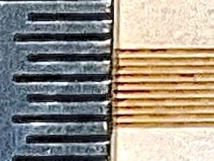
With about 8 lines in 1.5 mm, the line spacing is 0.187 mm, probably 0.2 mm = 125 DPI.
Each line has a dark core not quite centered along a lighter stripe. The stripe is about 2/3 of the line spacing, so call the overall spot 0.15 mm and the core maybe half of that at 0.08 mm.
The top group has 10 lines in 1 mm and you can barely see the darker core in the 0.1 mm spacing, so 0.08 mm is slightly too large.
Those numbers depend very much on the usual power / material / speed / spacing choices.
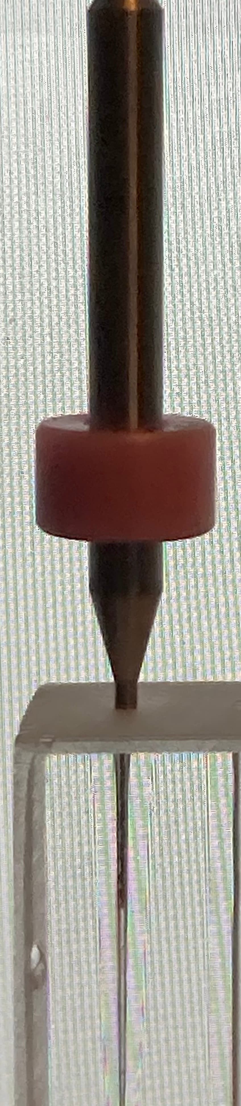
But, really, you should level up your instrumentation:
![]()
2 Likes
Thanks my friend, that’s what I wanted to confirm. I love doing practical tests and experiments, of course I have to get this little microscope, I have often needed it. Thanks my friend, that’s what I wanted to confirm. I love doing practical tests and experiments, of course I have to get this little microscope, I have often needed it.
Was air assist on?
Yes, it is always on, but there is only moderate pressure to keep the lens clean when there are no tough cutting tasks on the agenda.
I judged it to be a 0.1 dot on the ‘Y’ but I could not figure the ‘X’ axis…So I will say 0.8.
0.02 overburn from the core edge out because of heat or (beam dispersion?).
And is the air assist toward the back of the machine head/module.
I thought it was a line spacing test with equal spacing in the middle group.
85% line consistancy at low power in the top group…but the air assist helped with fill consistancy.
Thanks Peter for your input, but in the end I have found a very simple way to determine the precise spot size of a (my) CO2 laser. As @ednisley writes, I should have bought a microscope or a special magnifying glass, preferably with a scale, but I don’t have one yet.
By shooting for 5 seconds and with a fairly high power, at the top of an acrylic block, I get a “shot hole” that I consider to be precise in diameter.
Those who have tried playing with acrylic and lasers, know that there is a “neck” that starts at about 5-6mm below the surface (after the shot crater) and ends again after 5-7mm, before the balloon effect occurs, I think it can be clearly seen. The small section in between is considered to give a reasonably stable image of the laser beam’s diameter. The material that is evaporated and needs to come out of the hole, due to the temperature, expands the Ø itself a little, …0.5-0.1???
The conclusion: 0.5mm can be carefully pressed into all holes, 0.6mm cannot, with reasonable certainty I can state that my laser beam leaves a hole that is between 0.4 and 0.5 millimeters.
Spot size, measuring in this way, however, says nothing about how fine lines can be achieved. It is primarily dependent on power and speed (and spot size ![]() )
)


3 Likes
Thanks for the images Bernd thats quite interesting.
2 Likes