3D slice. I am getting 30 individual passes on this test. It does feel like each of these passes may be using some form of grey scale? Don’t know, as I’ve really only got my EzCad3 experience to work with and that was using actual STL’s not an Image.
Ah. I have a lot to say on that… there’s a lot of math and geometry involved, and decisions must be made. You need a model of the galvo’s setup, which is not complicated in itself.
Galvos can actually cut through thick sheets pretty effectively, but only inline with the center of the lens. The galvo beam cuts in a slanted cone, more slanted the further you get from the center.
The part where it’s easiest to see the problem is the furthest to the edge of the workbed, where the beam is slanted about 20 deg. And the focal cone of beam is about +/-1.5deg. To go deeper, the path leading to that depth has to be cleared out, which may already be removed in a relief anyways, but if not you have to decide whether the cutting algorithm should just leave the upper layers unaltered and discard certain deep parts as unreachable, or decide to carve enough out of the upper layers to clear the path to the lowest points.
I’ve done a fair bit of deep “milling” style operations and understand well the issue with (and what is possible) with 2.5d engraving including the issue with the cone and shadowing.
Take this crude example. I want to engrave out 2 deep square holes on my 2.5d Galvo. As Danny says, the shadow would prevent this from working if I tried to do it in one job (left hand side), but there is no issue doing this one at a time (right had side). One day I may get a true flying head 3D galvo which would give greater freedom as it can keep the beam vertical, but even then I’d have to ensure I did not have any undercuts.
Where I’ve landed is… it is up to the STL model design to take into account the limitations of the particular equipment rather than the engraving SW. To me LB should just execute the STL as it is given.

Can you elaborate on what you think could be improved?
Maybe share a link to a post that explains the issues you mention here, or start a new thread to explain what could be improved in terms of efficiency.
With the 3D-Sliced mode, each layer is processed at the constant “Max Power” setting.
From our docs:
Lighter pixels are engraved with fewer passes than darker pixels, resulting in a deeper engrave in darker areas of the image.
Whereas with Grayscale mode:
Grayscale varies power output as a percentage between Min and Max Power, using Min Power for the lightest shades and Max Power for the darkest.
Grayscale scans every portion of the image, just at varying levels of laser power.
Thanks - is there anything else you want tested at this stage (or need feedback on)?
Nothing specific. But feel free to keep using it, and let us know if any issues come up.
Will do (as I’ve purchased a lic already). Any hints on what features you are looking to include during this development cycle?
Certainly. I haven’t tried grayscale mode on the galvo in quite a while, but what I encountered was that Lightburn was handling it absurdly slowly. I switched back to EZCad2 and it handled it much faster. So the hardware wasn’t the problem.
I recall the issue seemed to the BJJCZ’s protocol hadn’t been reverse-engineered completely enough and LB was limited in the method it had available to send pixel-by-pixel power changes. The method it had was so slow that it wasn’t really a practical option under LB.
That was probably over a year ago by now- has it changed? I’ll go check when I get a chance.
I need to do some comparison between LB and EZCad2. To be honest, I have never been able to get LB to match the quality of engraving I got with EZCad2, and I really do think it mostly comes down to problems in the way LB tries to “sample” with 3d engraving slicing as described above.
The problem gets considerably worse when working from higher detail original art. There are always going to be limitations where the laser cannot render detail smaller than the spot size of the beam. There are some different ways to handle that but LB seems to be using the least appropriate solution and I don’t see a good workaround.
Working with a 300W M7 has given me a bit of a different experience. I have found managing the work’s surface temp is a key problem. I did come up with excellent solutions for this that will work well in Fill mode, but not in any Image mode. I did put in a detailed feature request on interlacing lines to solve this, went through details on how to implement it, but it never got off the ground.
But, interlacing and fixing sampling are actually two different things. LB’s clearly trying to sample the image with a square grid of widthless points, and that’s really not the right way to do it, and applying DWC on top of that won’t help it.
It’s not that hard to do this differently. I see you will be very concerned about backwards compatibility, so I’d suggest this actually be a different pulldown option entirely: “3d sliced 2” or something.
Basically each slice is a threshold for the current grayscale level, then trace into a vector fill, then offset shape inward by 1/2 the dot width and then handle it as a Fill. This won’t just fix these weird artifacts I showed with the above tests- it’s fixing very real quality problems you can get with the current 3d slicing solutions.
Anything relevant to this discussion in RC11?
Thanks
Nathan
I downloaded the the 2.1.00 RC-11 and It was easy to install the driver, but I found some issues with my laser. I do have a Haotian JPT 2.5D MOPA 60W.
Z axe still is needs work, the home and arrows icons work in the oposite way, so all my Z adjustments are made from: Laser Tools → Device Settings.
I can’t center the red beam coming out of the lens. I think stays in the last position and I rather see it in the center.
I see changes in the scales, but I will check them tomorrow with more time. huge improvements in this new release.
scales are perfect. now learning how to configure the new settings. I try to activate Q-Pulse for adjustments in the pulse width. seems like is not activated. is this correct? and if so, when do you plan to activated?
JF
Thanks, Danny, for the detailed information. I’ll pass it along to the developers who worked on these features to see what we can improve.


Q pulse is working now. I dont know why since I did not do anything different from yesterday.
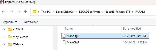

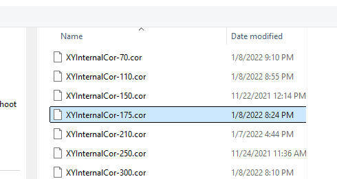

 Home works o.k. but arrows work in the opposite direction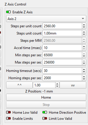
Check these videos
Thank you for the screenshots and the videos.
The motor noises sound like missing steps because of too many “steps per sec”.
Try increasing the “Accel time (msec) to 400 first.
If it doesn’t solve the skips, decrease the “Max steps per sec”
I’ve reached out to our devs about the inverted jog direction.
Please send us the Motors.ini file for investigation.