I have a Chinese blue and white 50W with topwisdom TL-410C controller, however after a month of light use it dropped power. Decided to replace the tube and PSU for a 90W.
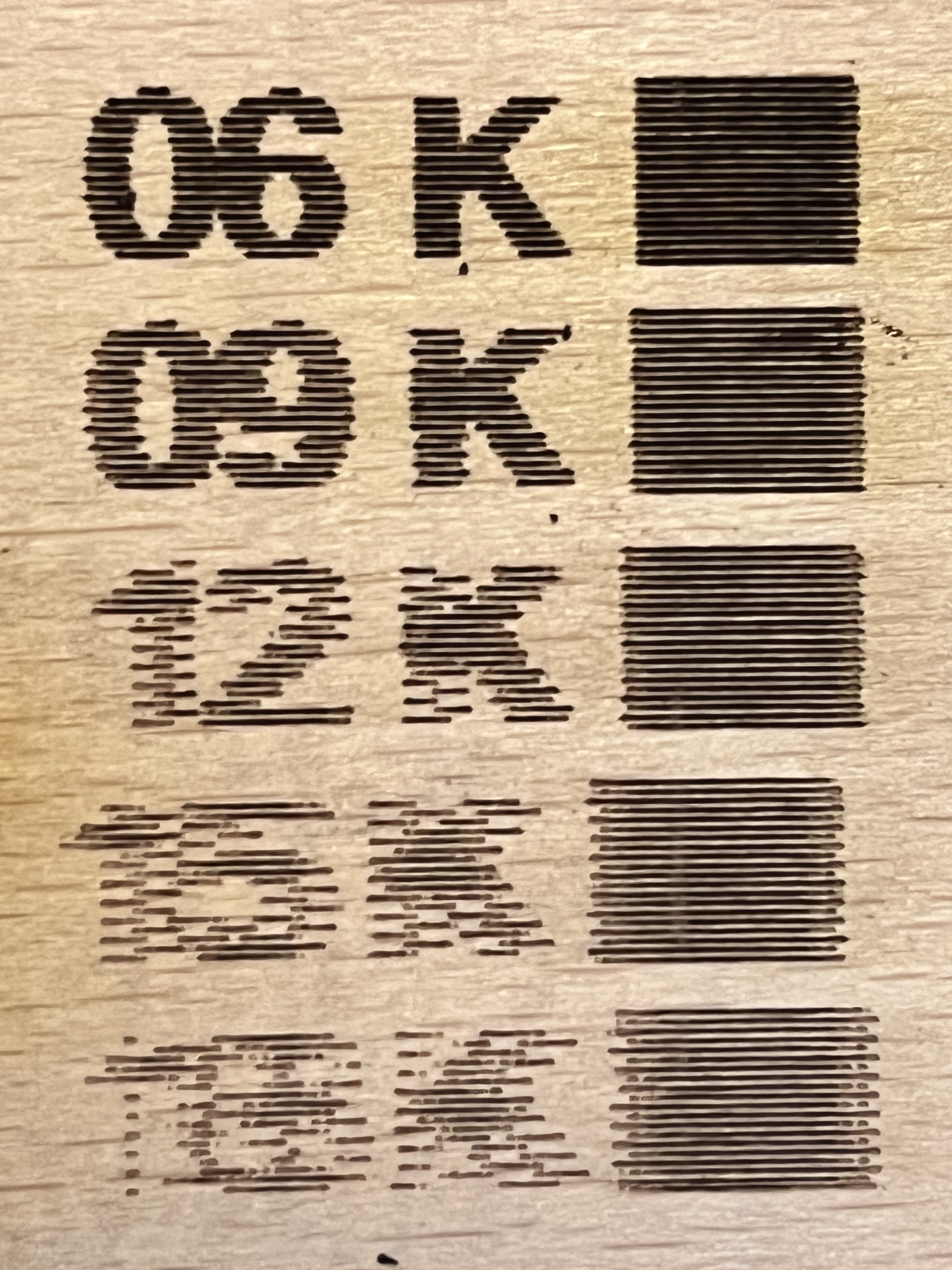
Just finished doing this upgrade and when trying material tests I’ve found an offset required at higher speeds, <9kmm/m it’s almost as if overscan isn’t working on the controller. I didn’t have this issue with it before the loss of power and upgrade.
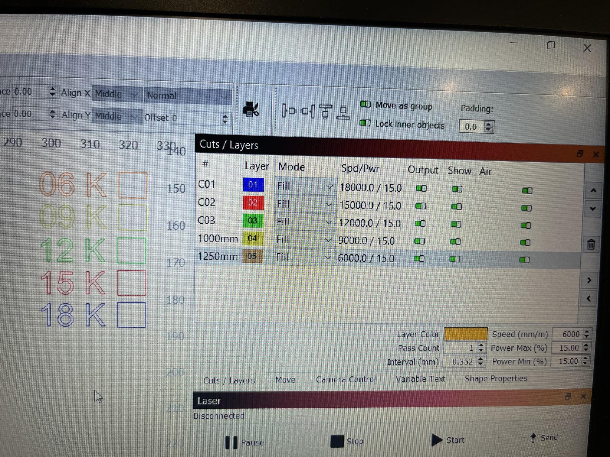
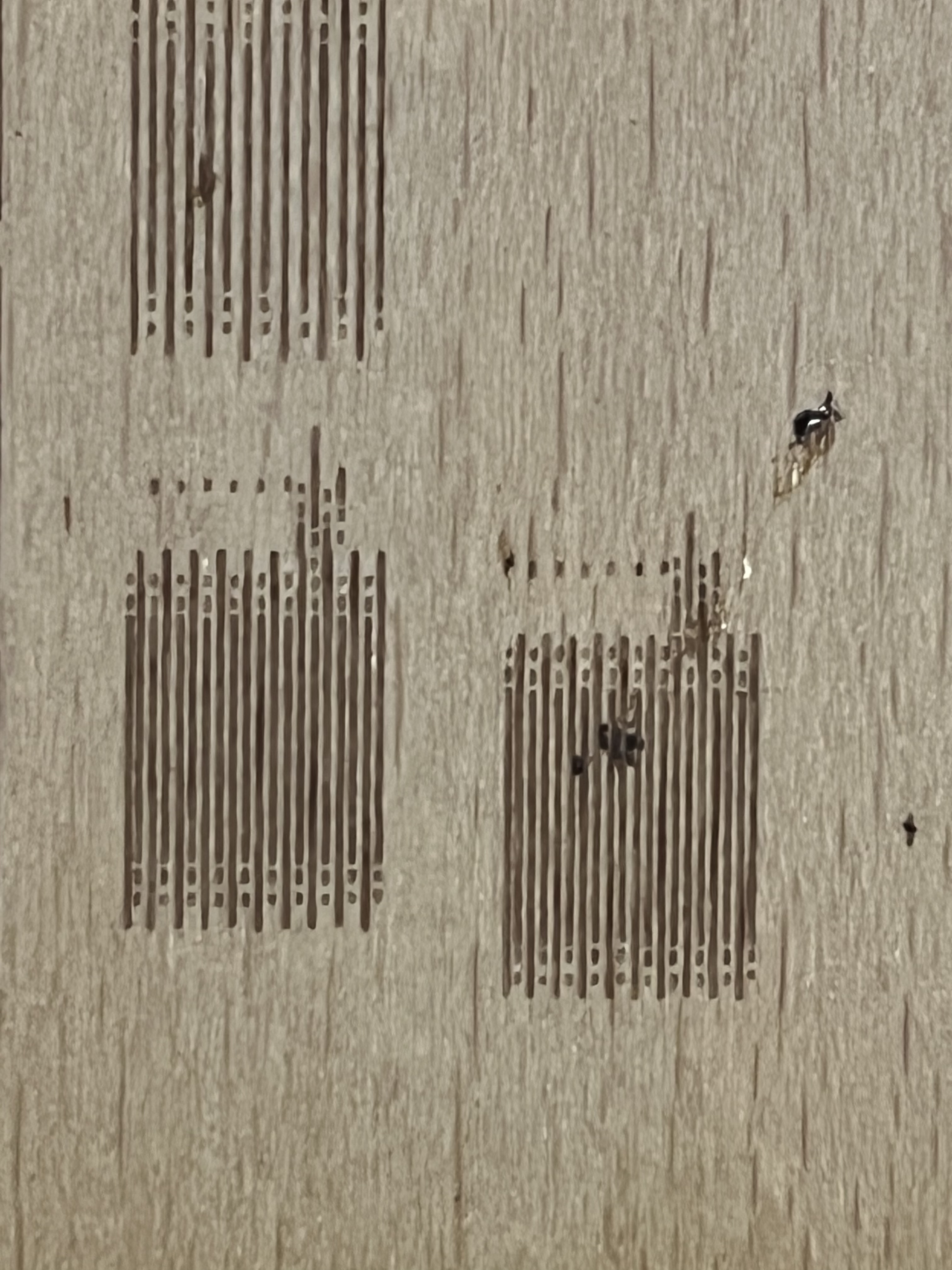
There’s definitely still work to do on the scanning offset adjustment parameters, but I’ve noticed at 12000mm/m onwards I see a dot or two at the start of the line. I’ve checked my min power setting on the topwisdom controller and it’s set to 15%, which is 6ma (tube min trigger current is 5ma)
For my 60 W laser, the offset correction became significant over 100 mm/s, so it’s not surprising (to me, anyhow) that you don’t need it below 150 mm/s.
The offset timing depends on the HV power supply timing, so it will be different with the 90 W supply. Measure and correct as needed!
That looks like a rather orderly version of the random dots I explored:
They’re probably on the tail end of the engraved line, where the tube has been lasing and the HV power supply can’t tamp down the tube’s conduction. You may get fewer dots when you run at higher speeds with higher powers.
If they happen with regularity on every engraved line, no matter what power you use, a warranty replacement seems appropriate. Definitely let us know how that works out!
Hi, thanks for the info - I’ve already been doing the scanning offset adjustments that was my first thought. At 18k my offset is going to be about 2.5mm - which seems huge compared with that documentation.
Even so, if it works it works! I don’t mind doing the adjustments, however if I’m still seeing those dots at the switch on of the line it’s going to ruin any engraving.
I wonder if there’s any settings on the topwisdom controller I’ve missed…
Thanks for the info, they seem to be pretty repeatable rather than random. I’m not sure if they’re on the lead in or lead out of the line - I’ll confirm that tonight that’s a good point.
How significant did your offsets become? At 18k I’m going to be looking at somewhere around a 3mm offset which seems big compared to some of the instructional info I can find.
I’m wondering if there’s something I’ve missed on the topwisdom controller I should have adjusted when changing the LPS.
Not sure how good cloudrays support is but I’ll also message them.
That’s 300 mm/s, so 3 mm is about 10 ms, which means the power supply is taking much too long to wake up.
The correction here is 0.15 mm (half of the total 0.3 mm). That’s about 1 ms, roughly the specified power supply risetime.
The TL-410C manual says (page 48) the controller has various laser timing delays that surely interact with the LightBurn settings in amusing ways.
If you set those to zero, you can measure the offsets with LightBurn. Use those numbers to calculate the actual on-off delay times, set them in the controller, and see if that improves the situation.
If not, then spin up their support, because something seems wrong with the stuff you just bought.
I’m revisiting the photos based on the latest posts.
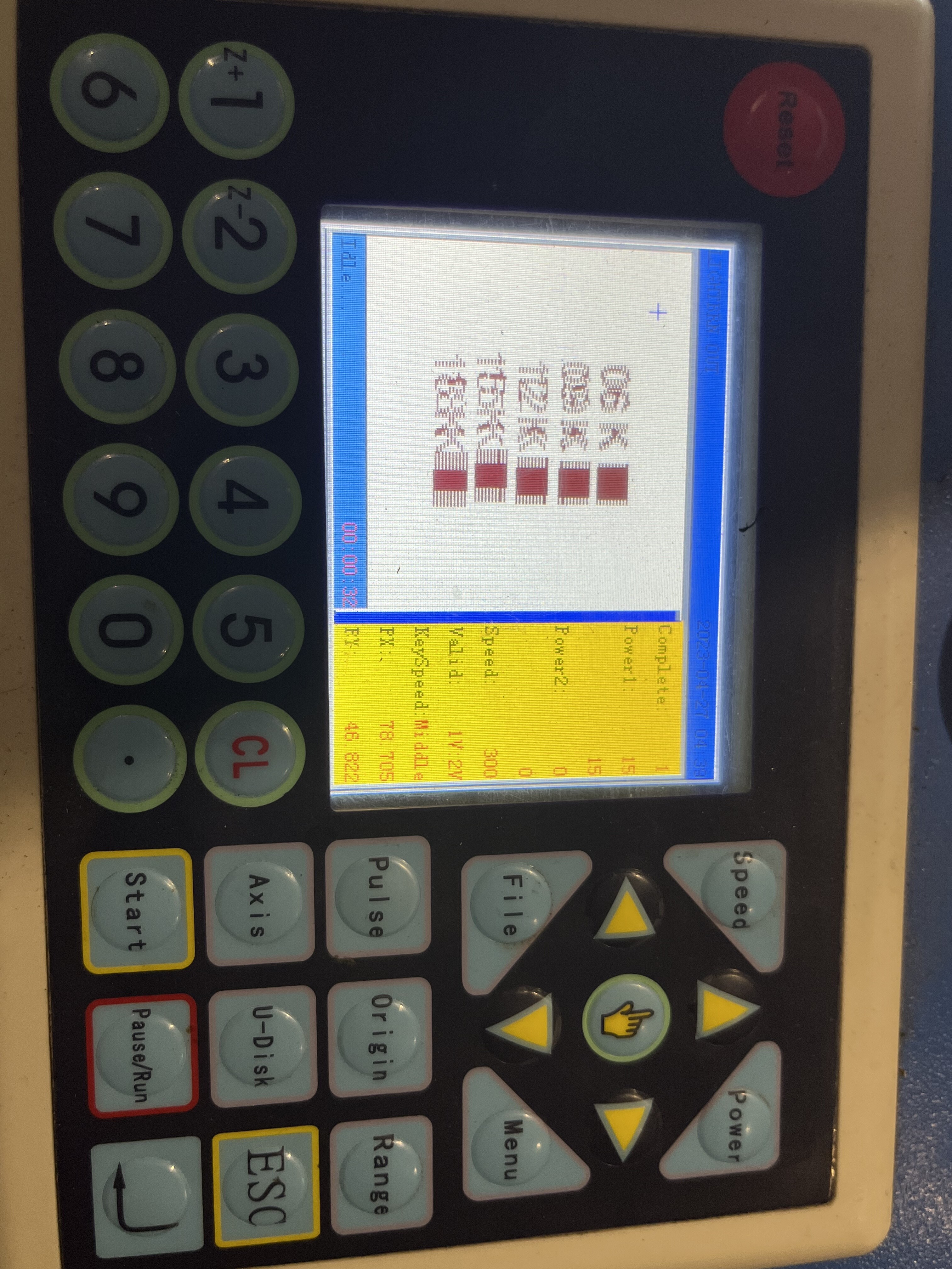
I didn’t initially realize that the display panel showed the offset. Is that the result of the scanning offset adjustment being applied? Or is that before the adjustment?
As for the dots I didn’t realize that was what you were referring to. They were so regular I thought that was a part of your design. There’s almost certainly something fundamentally wrong but uncertain as to what.
The timing information that @ednisley linked certainly worth review but suspect it won’t change the dot situation. If the values are non-zero can you take a photo?
In any case, I think a call into Cloudray certainly warranted.
If there’s no scanning offset adjustment put in the display will show the image fine. The offset on the display screen appears when I’m putting scanning offset adjustments in.
So either the display looks ok but the resulting burn is misaligned scan wise
Or I do the offsets, display looks terrible but resulting burn is fine.
I’ll play around with the controller settings for laser timing tonight and see what results that gives me, but I’m still not sure that the ‘dot’ will be resolved by any of these timing settings.
I’ve reached out to cloud ray for support. I’m not sure what the quality of their tech support/warranty is like… to be continued!
I’ll keep you all updating with results when toying around with the controller settings.
That makes sense, because LB tweaks the line positions it sends to the controller, so the lines “come out right” in the material. The adjustments aren’t normally visible on the tiny controller display, but in your case they’re huge.
Disabling the LB adjustment and setting the timing in the controller should show the unadjusted lines on the display (because LB is not tweaking them) and produce good (well, better) results (because the controller is doing the tweaking).
None of this will affect the random / regular dots, which definitely suggest the power supply is having trouble. Combine that evidence with the too-long delays and the conclusion is the power supply isn’t doing what it should.
Trying to get Cloudray to look into this, they’ve done some testing and came back saying offset adjustment is all they can suggest. The reason it is off and for the ‘dot’ is a frequency difference between the LPS and the Motherboard (I’m assuming they mean TopWisdom controller here)
I can adjust the PWM freq on the controller, if this is the frequency they’re referring too. When I asked them what the freq value of the LPS was they said they don’t know.
They’ve asked me to send some results of tests ran at 0 and 90 degrees which i’m running now and sending them. Of course it’s the same on both scan angles.
I’ll update you all of how I get on, hopefully if I resolve it others may too.