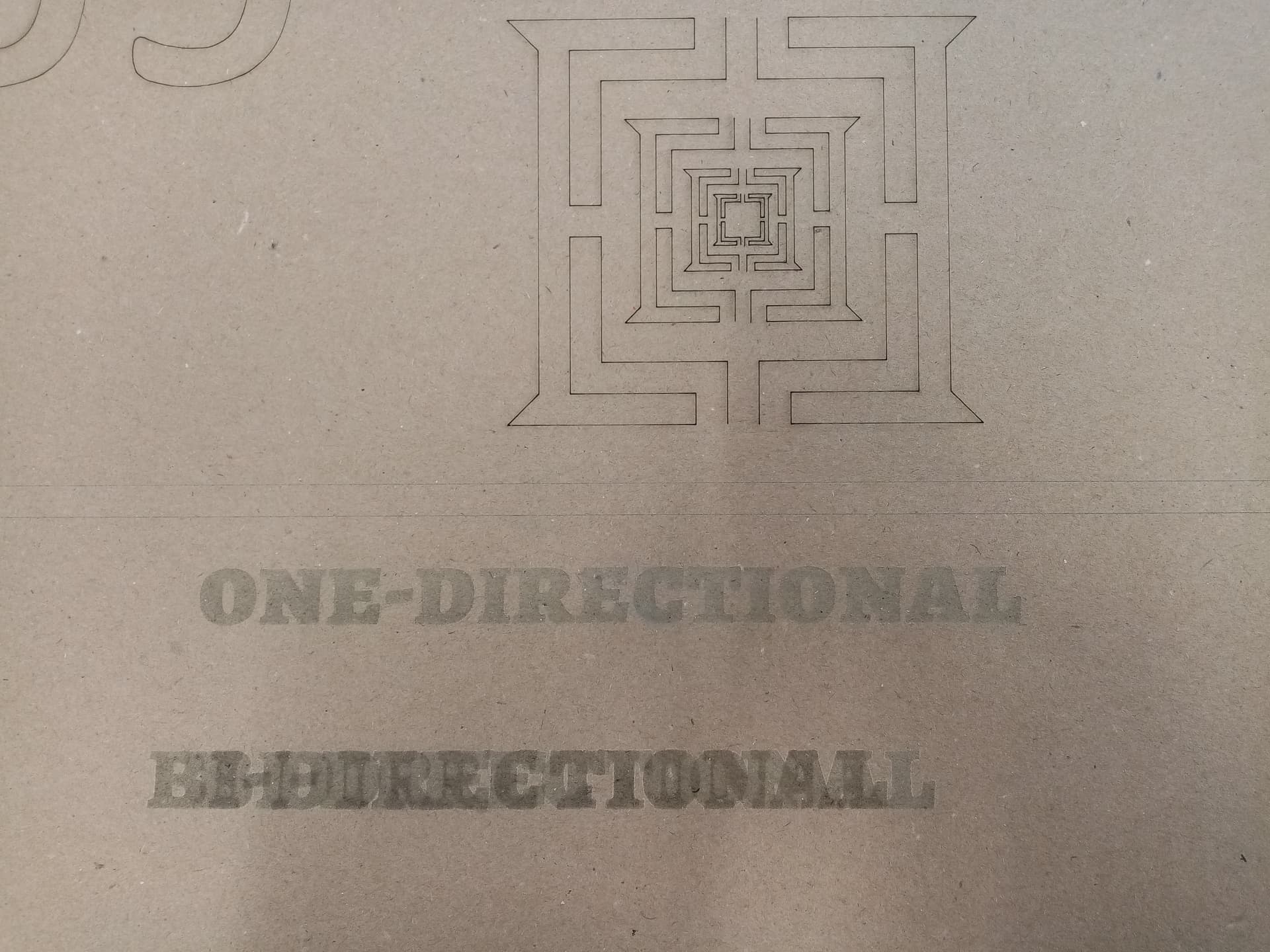
I just got a brand new 1610 CO2 laser and attempted to engrave for the first time. My engraved text came out double with about 10 mm offset. It cuts OK, this only happens when I am engraving with bi-directional scanning enabled. When disabled it engraves OK, but it takes twice as much time. It happens when engraving in X-swing and Y-swing as well.
I read in the forum that one user had the same problem and solved it when tightened the belts. But my belts seem fine and not loose. Also it happens only when engraving bi-directionally. If the belts where the issues (or loose lenses) it should not be able to engrave correctly when bi-directional engraving is disabled. BTW the same happens both in Lightburn and in RD Works.
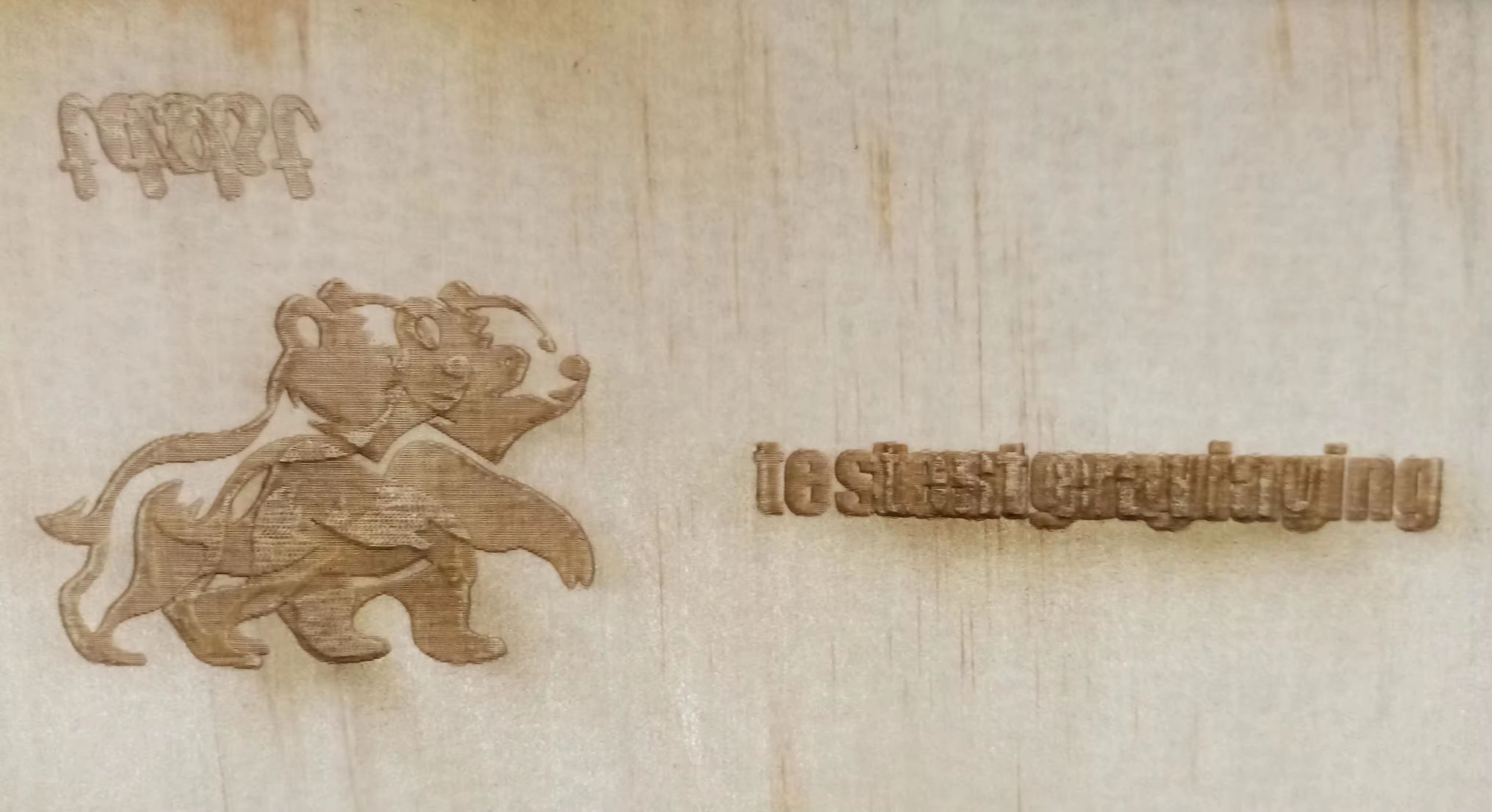
I am attaching a photo of the output. Any help will be greatly appreciated.
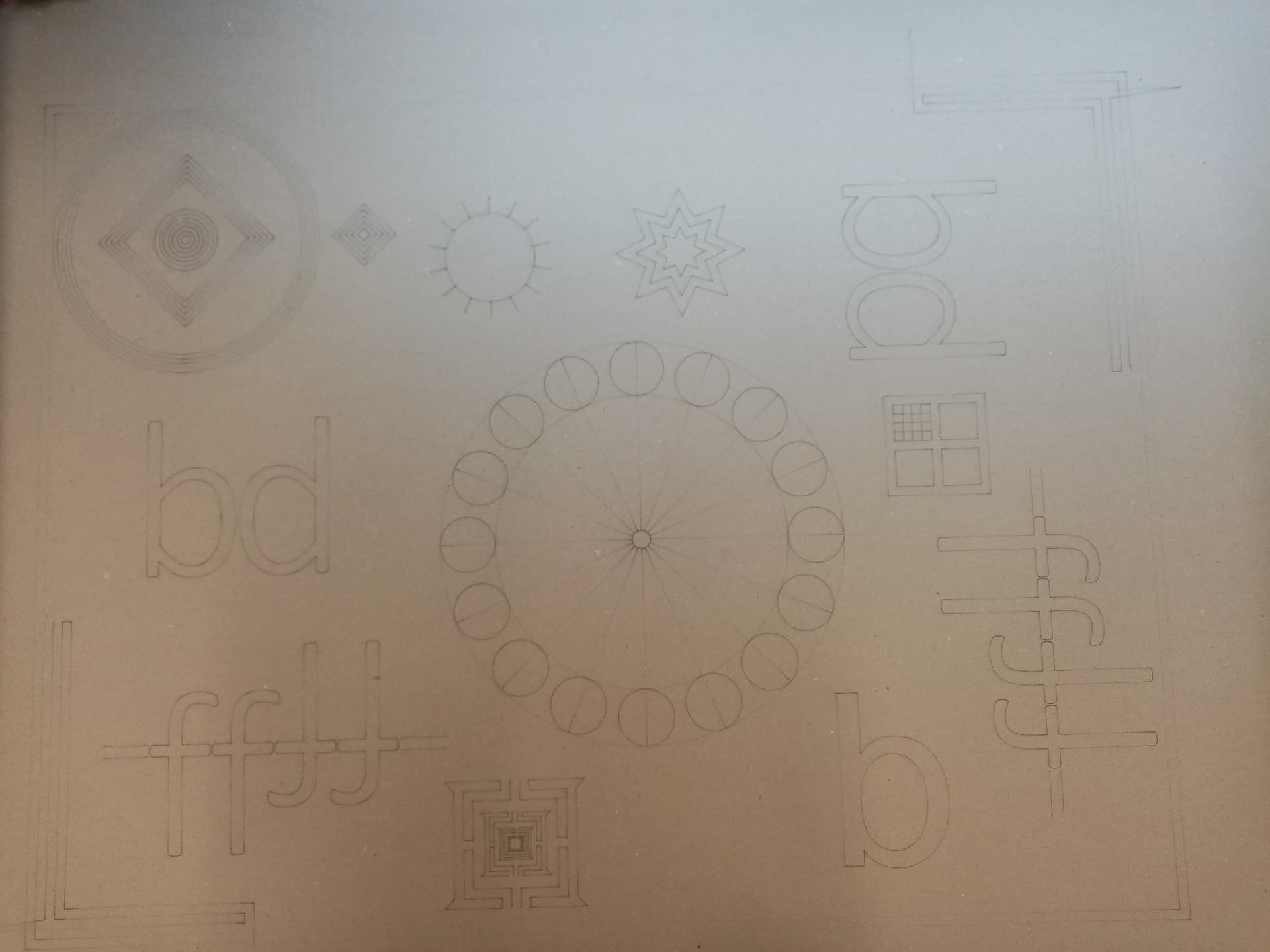
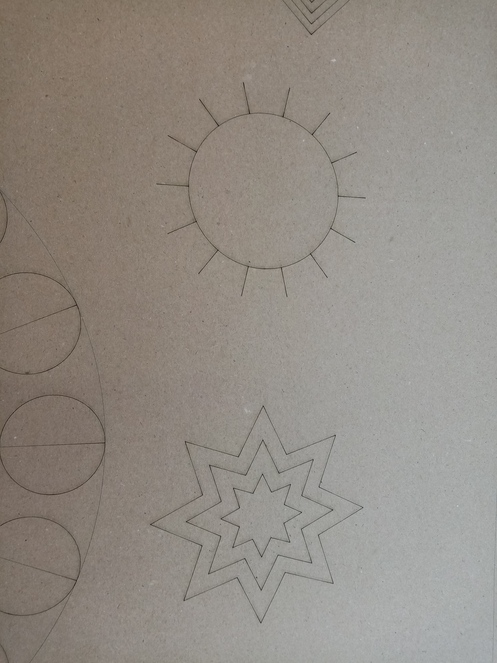
Scale that pattern uniformly to fill the platform and run it as fast as it will go in Line mode with optimizations turned off and power set to mark a sheet of cardboard. Any differences from the design will be informative; a photo will let us look over your shoulder.
Thank you for your input. I am not sure I understand all of your instructions. Do you mean I have to expand the provided design to all of my workspace (in this case 1600x1000 mm) and engrave it on a cardboard? I am not also sure what “Line mode” is referring to?
The intent is to make the lines long enough to allow the machine to reach full speed, as opposed to short lines where it’s still accelerating. Half a meter on the long side should suffice for your machine.
Because cardboard is cheap and readily available.
Some folks insist on burning through their stock of irreplaceable walnut veneer while debugging problems, but we try to discourage that.
Line layer mode tells the machine to follow each of the lines, as opposed to Fill mode that scans across the pattern as an engraving.
In this case, we want the machine to undergo irregular direction changes at high speed, so we can verify its ability to do so.
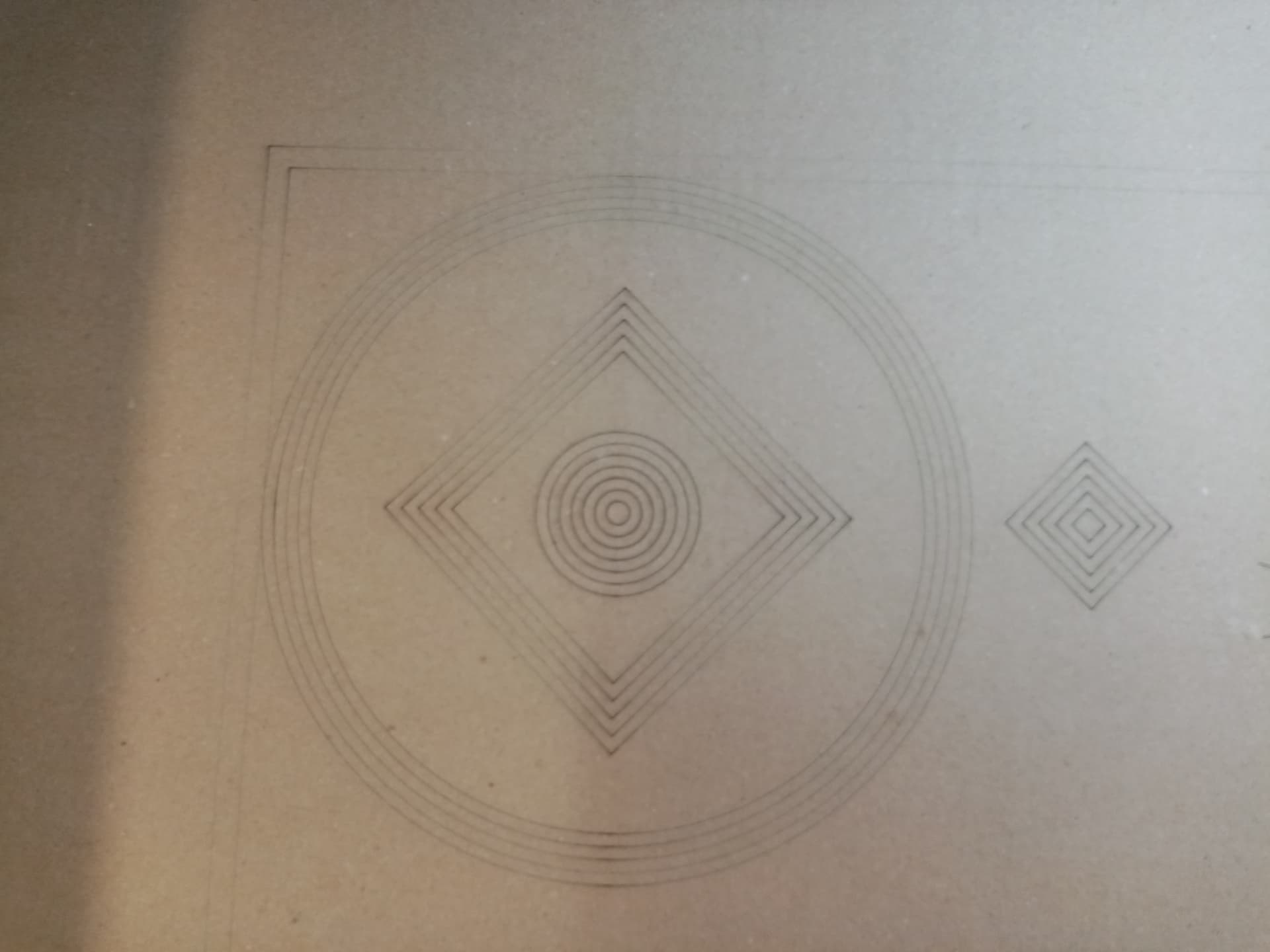
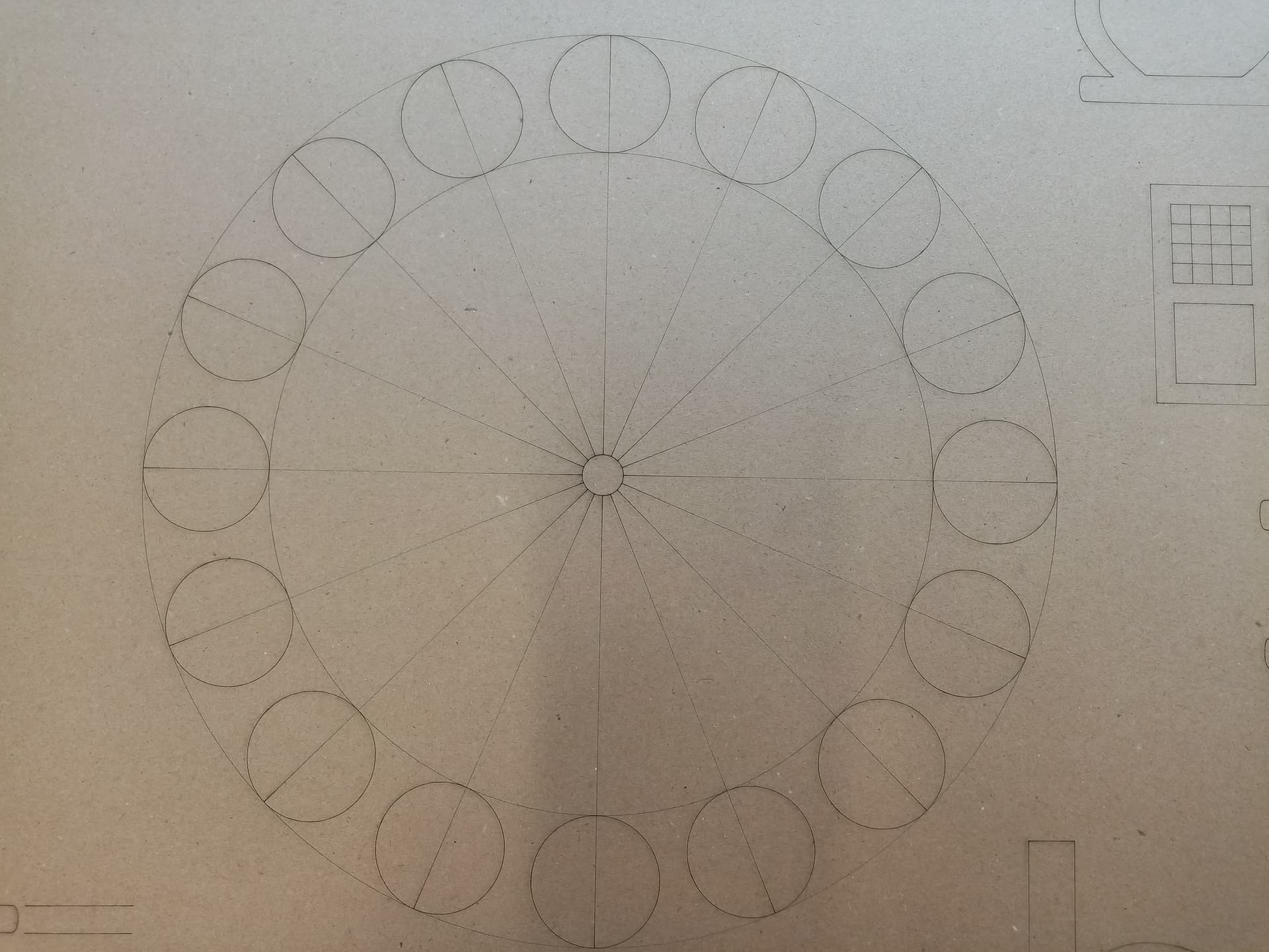
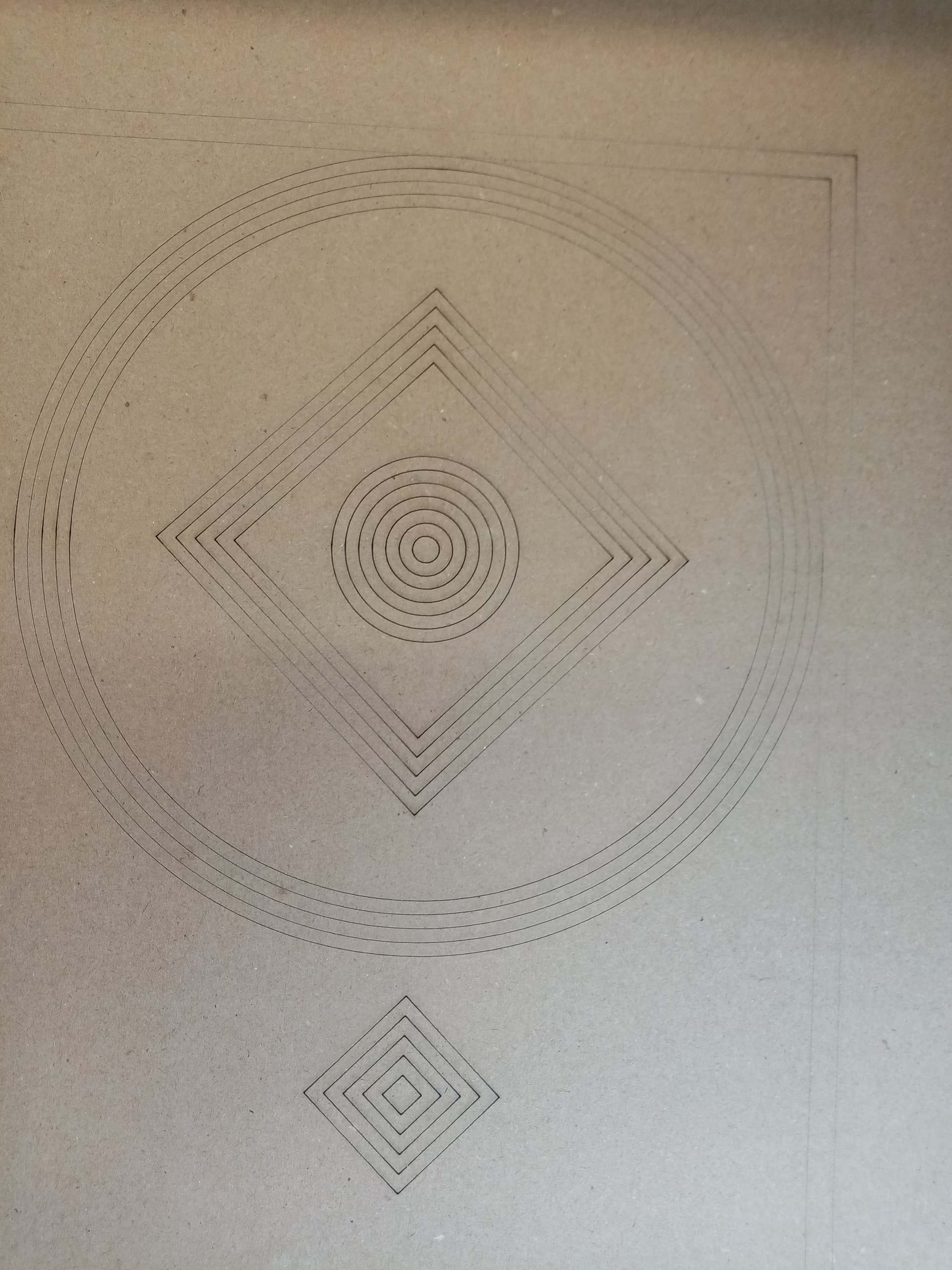
As expected these results are flawless because it is in line mode, which is the cutting mode. As I mentioned in the beginning I do not have problems when cutting. Only when engraving in bi-directional mode.
The manufacturer of the machine suggested that I do “reverse compensation” in RD Works. This did not help, because no matter what value I entered for compensation the offset only got worse, not better. In fact with 0 value compensation the result was with less offset. I tried positive value and negative value, both produced MORE offset and would not fix the issue.
Yes. A 130W and 300W tubes. Both heads engrave with the same problematic “dual vision” offset when engraving in bi-directional mode.
Yes.
Yes.
When doing the test engravings - yes.
Not in Lightburn yet, because I am not sure my version (1.3) supports this. But this is exactly what I did in RD Works and it did not help at all. Only made matter worse (bigger offset, as I explained in my previous post).
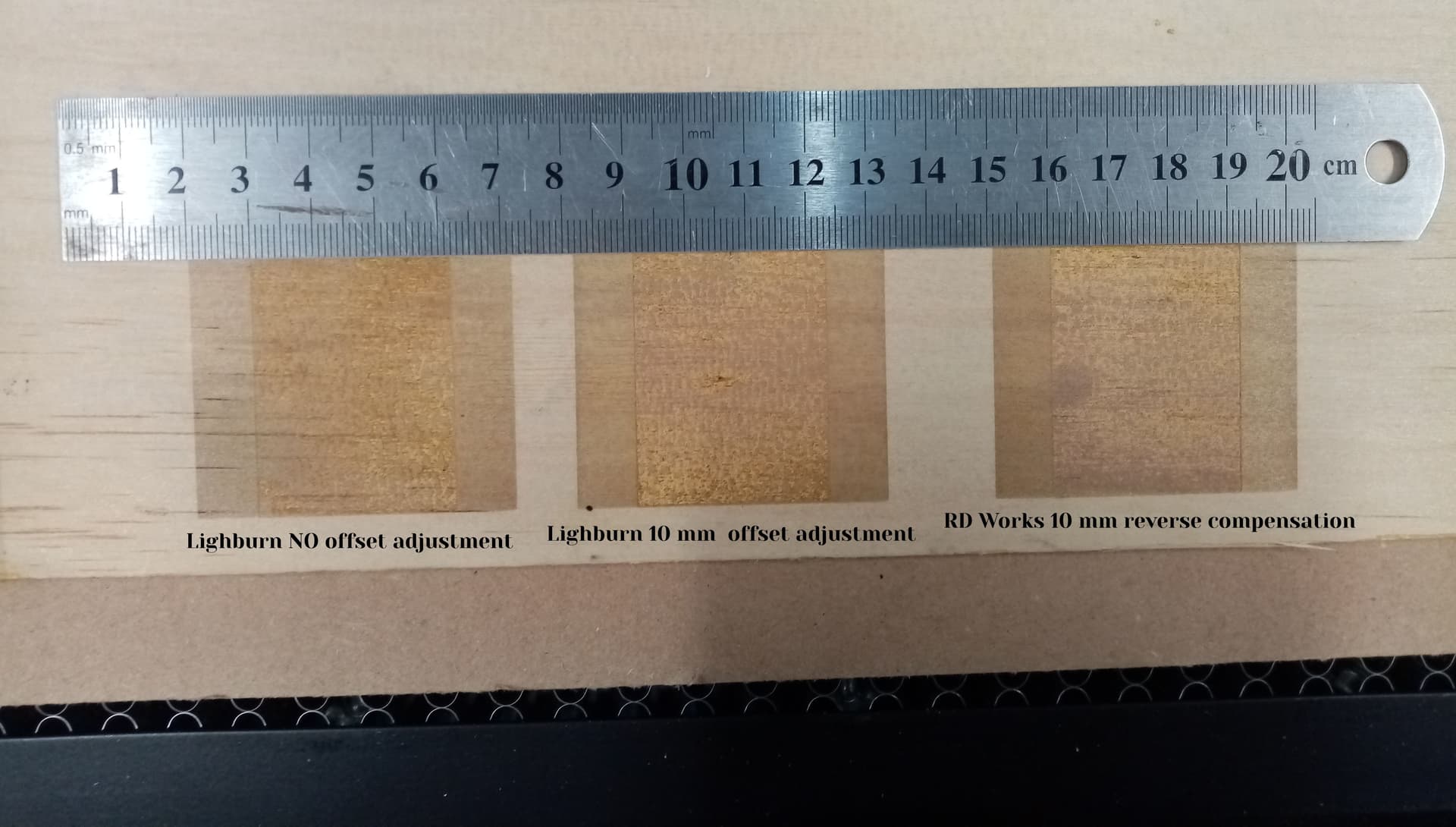
This is the result from the square test. I did 42 mm square and then run it at fill, 1000 mm/s.
Then did with no offset compensation, with 10 mm offset compensation in Lightburn and with 10 mm offset compensation in RD Works. The compensation settings changed nothing, as the offset remained the same at 10 mm.
Does the offset change at different speeds? Run that same square at 250 and 500 mm/s.
Different offsets would be the typical behavior, but the power supply timing is fractions of a millisecond rather than the 10 ms (10 mm / 1000 mm/s) in those photos, so I don’t expect the speed will matter.
AFAICT, we’ve eliminated all the easy problems, so it’s time for an expert.
@LightBurn: What obvious problem are we overlooking?
It seems that on top of the above discussed problem there is a 4.83 mm offset between cutting and engraving from the same head that is not affected by any offset settings. I am forced to offset my graphics by 4.83 mm in order to get the correct position of the engraving when engraving and cutting.
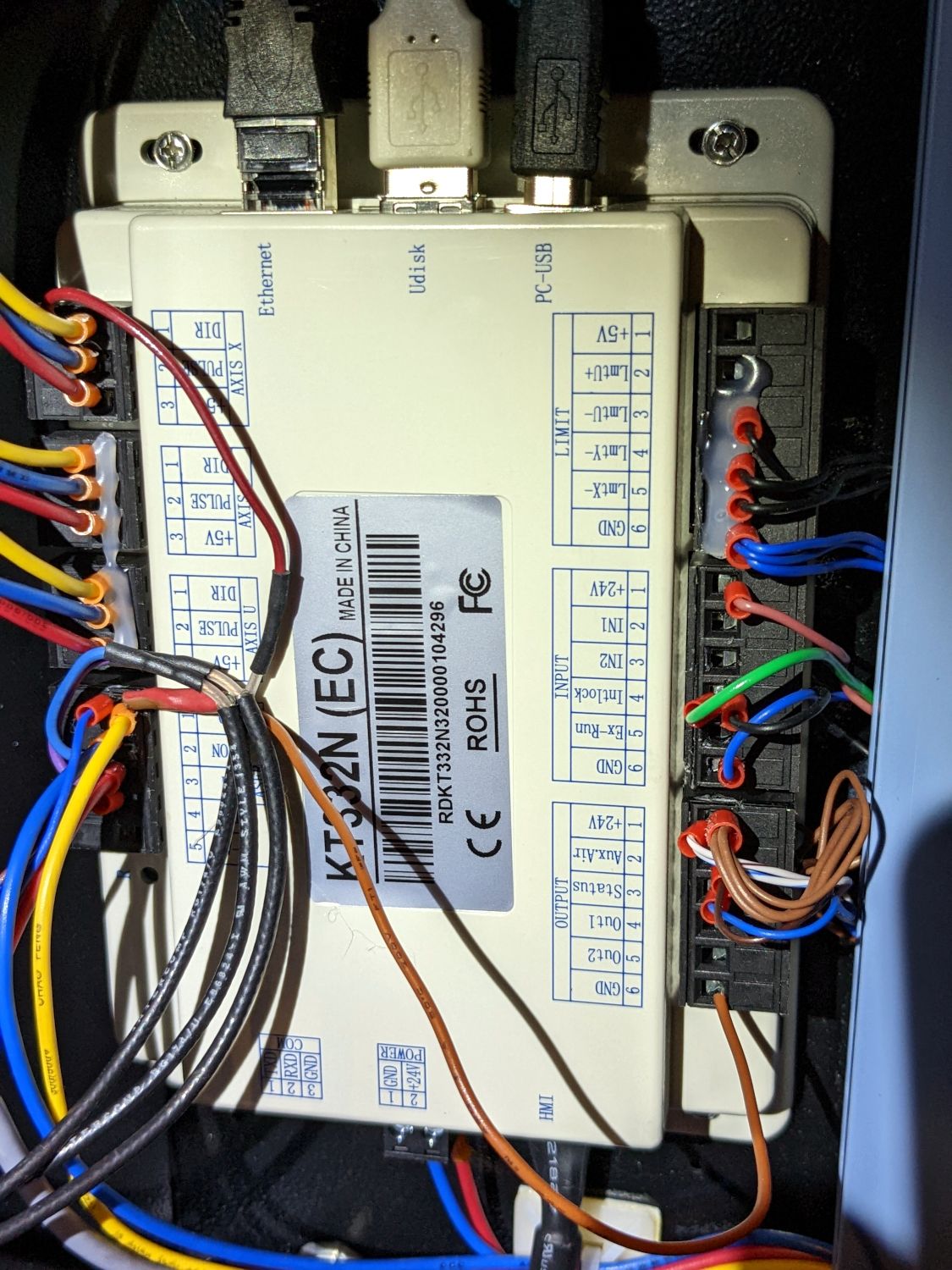
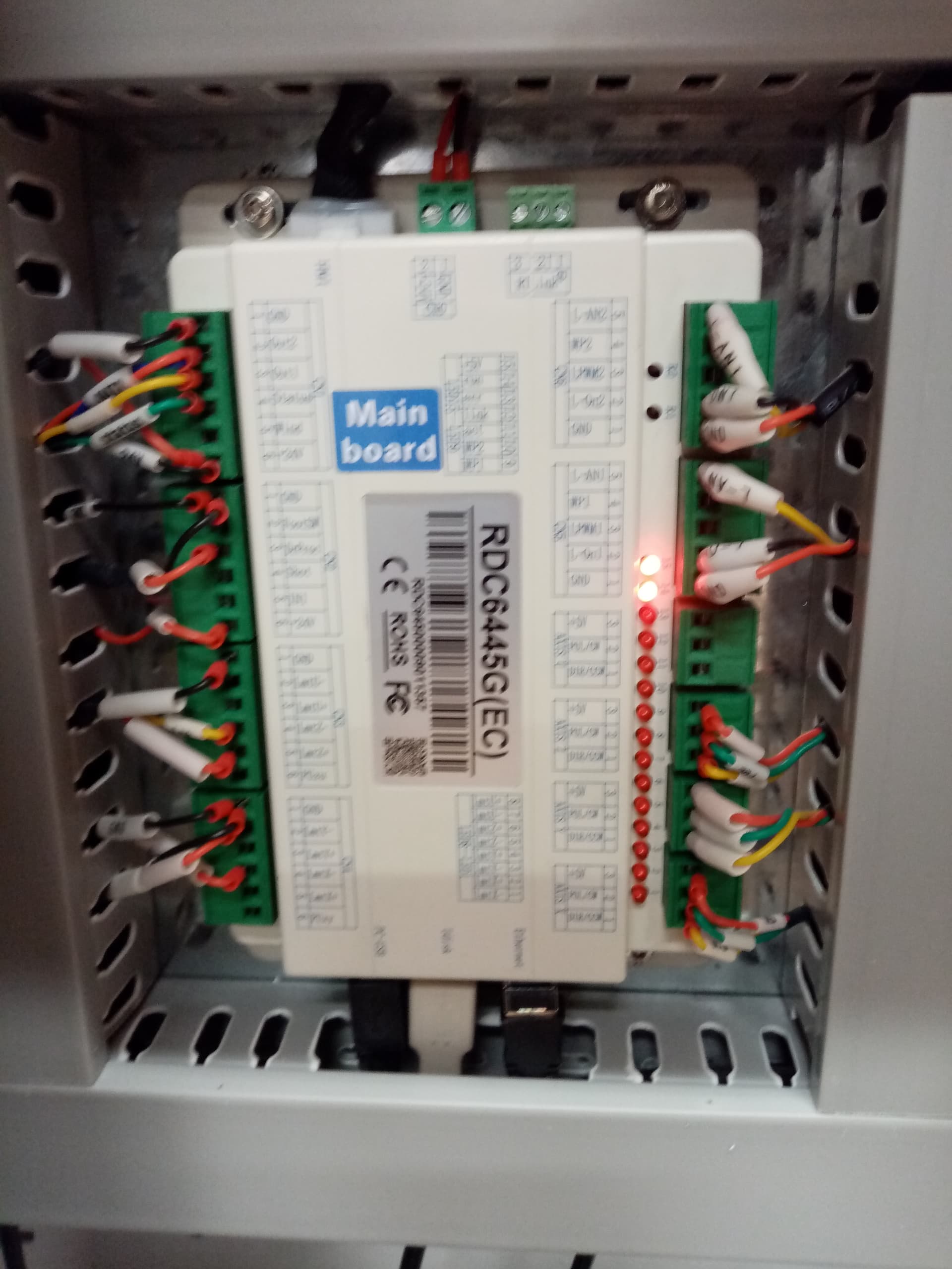
Could these problems be hardwired in the controller itself?
Here is a solution offered by a Chinese laser manufacturer (not the one who made my machine, they seem to be clueless):
If a CO₂ laser machine using a Ruida control board experiences misalignment, ghosting, or uneven edges during bi-directional engraving (Bi-dir), 99% of the time it is due to the “backlash” not being properly adjusted
Break the problem into three steps to quickly identify and solve it:
First, confirm whether it is “electrical-mechanical” or “laser-delay.”
Temporarily disable two-way engraving in RDWorks / LightBurn and perform only one-way engraving. Run the same graphic once from “left to right” and once from “right to left”:
If the two graphics are still misaligned → mechanical gap or loose belt, first tighten the belt, replace the slider, and adjust the gear set screw.
If the two graphics completely overlap → Pure electrical/laser delay issue, proceed to Step 2.
Measure the laser “switching delay” and write it into the reverse path compensation.
① Set the “reverse travel compensation” to 0 first;
② Draw a 50 mm × 5 mm rectangle, fill it with a 0.1 mm spacing, and run a line in both directions;
③ Use a microscope or a mobile phone to magnify and observe: If the left→right line and the right→left line are misaligned by ΔX mm overall, then
Reverse travel compensation = ΔX × 1/2 (unit: mm, enter a negative value if the direction is opposite);
④ Enter the calculated value into “Manufacturer Parameters → Backlash” and make sure to reset the motherboard after saving for it to take effect.
Fine-tune the “laser on/off delay” to ensure the beginning and end are aligned.
If the start/end point of the graphic still shows a “matchstick tip” or a gap:
RDWorks: In “Layers → Advanced,” set “Laser On Compensation” to +0.2-0.5 mm and “Laser Off Compensation” to -0.1-0.3 mm;
LightBurn: In “Device Settings → Additional Delay,” add 1-4 ms to “Laser ON/OFF” on each side, and observe which side burns more; reduce the delay on that side.
Supplemental Experience Points (RDC6445 / 6442G, 60 W Glass Tube):
Reverse stroke compensation 0.18-0.25 mm;
Laser turns on for 1.5 ms, turns off for 0.8 ms;
The scanning acceleration is ≤ 8,000 mm/s², and problems are most easily detected at a speed of 300-400 mm/s; adjust first and then increase the speed.
I haven’t tried it yet. Still have to try and understand the described steps. Does any of you understands this process as described above?
That’s basically what you’ve already done: eliminate mechanical problems, then compensate for power supply delays.
Given the amount of offset, something is badly wrong with the laser. You noted “It happens when engraving in X-swing and Y-swing”, which rules out essentially all mechanical problems; the test pattern confirms that.
If it were my machine, I would:
Reset all the timing adjustments to zero
Replace the high-voltage power supply (or supplies)
That will be moderately expensive, but AFAICT there are no other places for that delay to hide.