Drawing a grid the size of my burn area

I have a 40" x 40" laser and if I’m correct that gives me a 1016 mm x 1016 mm burning area. If that’s incorrect please let me know.

I’ve searched the forum about how to do this and I guess I’m using the wrong search terms.

I can get the horizontal line and the vertical line the correct length but after that when I bring up the grid tool and set columns and rows nothing happens.

Is there a video on how to use the grid tool?

Thanks for any help.

You are wanting to put a grid on a “waste-board”. Have a look below for how to do what you are wanting to accomplish.

And the video for “grid tool”. We call these tools Array Tools

Here is our documentation on the topic: https://lightburnsoftware.github.io/NewDocs/ModifierTools.html#grid-array

I have seen that video and I guess I could make that with the shape of the products I want to put graphics on. What I’m trying to do is actually print the grid that’s on the screen as the work area.

I hope that makes sense. I used to be a welder and made jigs for repeatable parts that needed to be put together the same. So I thought if I could have an alignment grid that would be great. That’s why I want my base plate to look like the work area.

I could just burn rectangles on there but then it’s a one use board.

Thank you for the post,
Ernie Hodge

Rick,

I thought that my 1016 mm was correct and thanks for the link to that calculator.

Ernie Hodge

Yes, that is what I am showing you in the link I provided.

The only thing that is missing is the outlining rectangle which you could add. The spacing of your grid is controlled in the ‘Array’ dialog settings at the time you generate the grid pattern.

tl;dr: draw two lines, use array to build the spaced grid, draw rectangle if desired, set layer to ‘Line’ with appropriate speed and power for your system, burn, enjoy new grided waste-board.

Is this not what you are trying to do? :slight_smile:

Rick,

Yes, that’s what I’m trying to do. I’ll try and follow your instructions and see if I can make that happen.

I did make a grad using rectangles which will work for my projects. But I wanted a plain grid burned for other things that will be various sizes and shapes.

Thanks for the help and I’ll let you know how I make out on the grid,

Ernie Hodge

OK, My mechanical brain isn’t getting what your engineer brain is saying.

I drew a line on top of the display grid and then drew another line down the side. I could only select one line and the grid array window will not open.

If I make one that goes from the trop left and then down the right side it will let me select that. Then when I put in 10 columns and ten rows it built a HUGE grid to the left and down from the display area.

I forgot to add that it is using the entire display grid as the first cell in the upper right of the grid.

What am I doing wrong?

Let me try again, this might take a few edits to get it all posted so give me a few…

Start by drawing a line. I made one the length of the bed which for this laser is 900mm. I placed it on the workspace as shown:

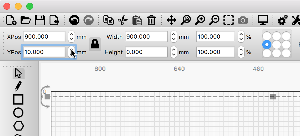
With that line selected, click the ‘Array Tool’. image

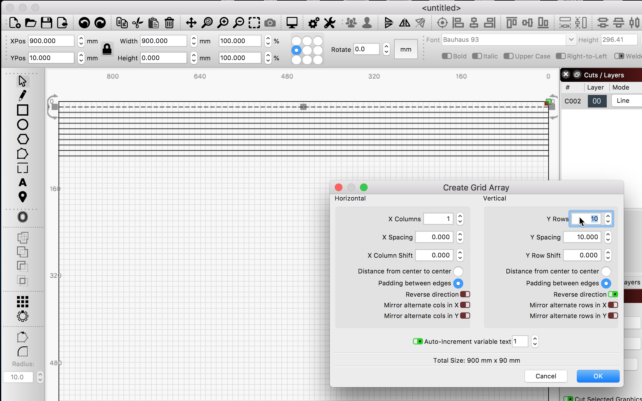
Start to increase the ‘Y Rows’ to see the line duplicated on-screen. Note the Y Spacing, I set it to 10mm, which matches my workspace grid spacing.

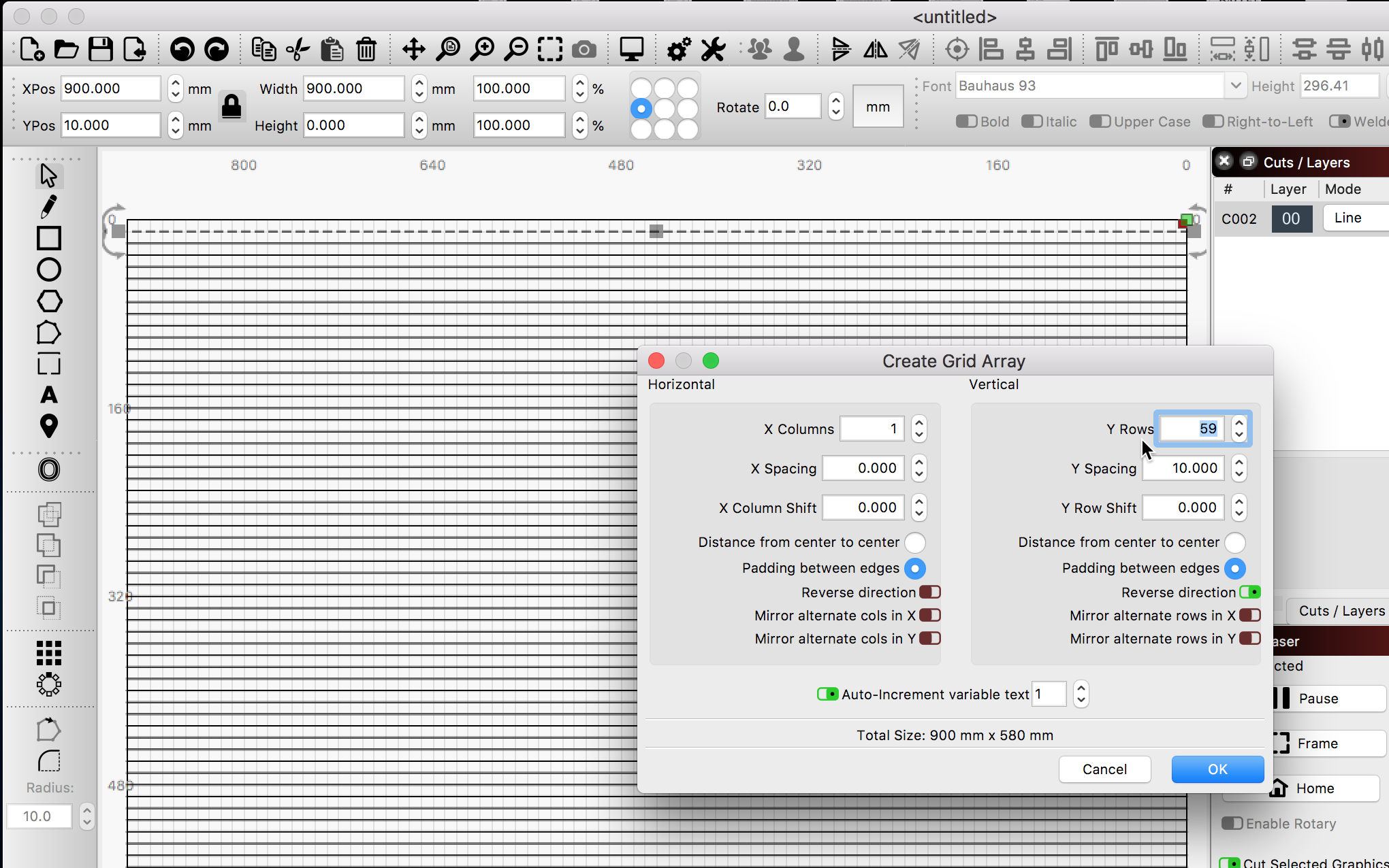
Here I finished this part with a total of 59 lines. Click the OK button when you get what you want.

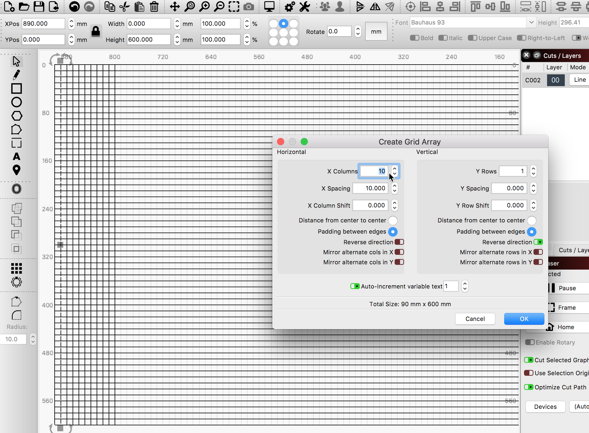
Now, we are going to do the same for the X row grid marks. So we draw another line, in this case, 600mm long and as shown below. Now, we repeat the process we did above. With the line selected, hit the Array Tool again, but this time we are going to make adjustments to the X Row and X Spacing to match the workspace for the X row marks, filling the rest of the array.

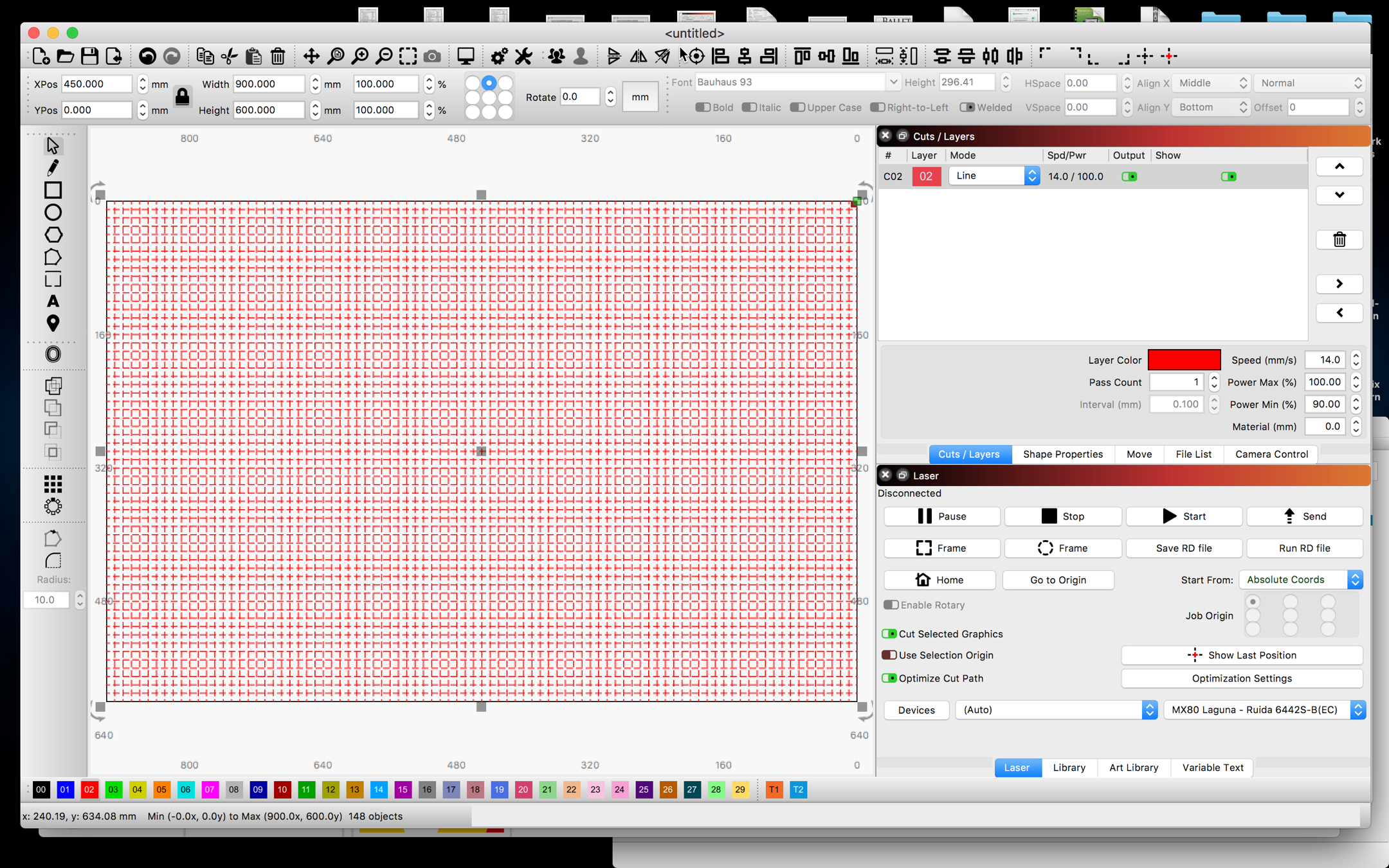
You have now built a matching grid.

You can temporarily turn the workspace grid off in the settings to better see your work, then turn it back on for your regular work.

Here it is after I turn the workspace grid Off. Selected all lines then changed them to the red Layer to see the resulting grid easier.

2 Likes

Rick,

OK, I just did that and it worked great. I have one question about the work area and I’m fairly sure it’s going to be a setting somewhere. When I try and work from left to right making this grid and I add vertical lines the lines add to the left and not the right. Is this a setting and if yes where?

I also think I’m OK now with the grid thing.

Thank you very much for helping me with this,
Ernie Hodge

You can reverse the direction of the building of an Array using the ‘Reverse direction’ switch to do what you are wanting. Flip that to change direction of build, adding the new lines to the right.

2 Likes

Thank you, I didn’t know that’s what that was for. I learned something new today and now I can stop and wait for tomorrow. :grin:

1 Like

This topic was automatically closed 30 days after the last reply. New replies are no longer allowed.