I have the OMTech K40+ Smoothieware controller. In general, it’s been good and reliable.
Unfortunately it’s relatively new, so support for it isn’t amazing yet.
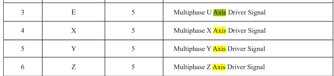
I built a Z-table, and I can’t drive the motors running from the Z axis port on the board. Apparently they only put 5 volts on the Z port. Their support tells me they put 24V .6A on the E axis port.
The question is, does anybody have any idea how to control the E axis port for Z table functions in LightBurn?
Side note, for anybody considering this board: it’s been reliable in general other than Z table needs. Once working with Z table stuff, it’s questionable. First, not enough power, and second, it has issues hanging when sending console commands from LightBurn. If I send a config_get command, it might work once, but after a 2nd or 3rd command is sent, I need to disconnect USB, and power cycle the laser to get communication back.
I think you might have better luck trying to see if you can reconfigure the E port to work as Z. Not certain but looks like this is configurable in Smoothieware.
You would need to identify the pin associated with E axis and assign with gamma_step_pin:
gamma_step_pin 2.2 # Pin for gamma stepper step signal
gamma_dir_pin 0.20 # Pin for gamma stepper direction
gamma_en_pin 0.19 # Pin for gamma enable
This way LightBurn would be none the wiser and would use Z as normal. The board would then just use “E” port for Z axis moves.
Unfortunately, not there. The config has alpha, beta, gamma with pin numbers, then it has delta, epsilon, zeta with no pin numbers (all say xx). The latter 3 say A, B, C axis, so it would be guessing which is supposed to be E anyway. The board just says 1a 1b etc., no pin numbers.
Stepper module pins ( ports, and pin numbers, appending “!” to the number will invert a pin )
alpha_step_pin 2.0 # Pin for alpha stepper step signal
alpha_dir_pin 0.10! # Pin for alpha stepper direction
alpha_en_pin 0.11 # Pin for alpha enable pin
alpha_current 0.4 # X stepper motor current
alpha_max_rate 24000.0 # mm/min
alpha_acceleration 2500 # mm/sec²
beta_step_pin 2.2 # Pin for beta stepper step signal
beta_dir_pin 0.21 # Pin for beta stepper direction
beta_en_pin 0.20 # Pin for beta enable
beta_current 0.6 # Y stepper motor current
beta_max_rate 24000.0 # mm/min
beta_acceleration 2500 # mm/sec²
gamma_step_pin 2.1 # Pin for gamma stepper step signal
gamma_dir_pin 0.19 # Pin for gamma stepper direction
gamma_en_pin 2.8 # Pin for gamma enable
gamma_current 0.6 # Z stepper motor current
gamma_max_rate 24000.0 # mm/min
gamma_acceleration 2500 # mm/sec²
A axis
delta_steps_per_mm 157.5 # may be steps per degree for example
delta_step_pin xx # Pin for delta stepper step signal
delta_dir_pin xx # Pin for delta stepper direction
delta_en_pin xx # Pin for delta enable
delta_current 0.6 # Z stepper motor current
delta_max_rate 12000 # mm/min
delta_acceleration 1000 # mm/sec²
B axis
epsilon_steps_per_mm 100 # may be steps per degree for example
epsilon_step_pin xx # Pin for delta stepper step signal
epsilon_dir_pin xx # Pin for delta stepper direction
epsilon_en_pin xx # Pin for delta enable
epsilon_current 1.5 # Z stepper motor current
epsilon_max_rate 300.0 # mm/min
epsilon_acceleration 500.0 # mm/sec²
C axis
zeta_steps_per_mm 100 # may be steps per degree for example
zeta_step_pin xx # Pin for delta stepper step signal
zeta_dir_pin xx # Pin for delta stepper direction
zeta_en_pin xx # Pin for delta enable
zeta_current 1.5 # Z stepper motor current
zeta_max_rate 300.0 # mm/min
zeta_acceleration 500.0 # mm/sec²
lol, if it says it on the other side, I’ll never find out. I’m not unmounting it.
I did ask OMT’s tech to find out the pinout. But the boards were made for OMT, not by OMT, so they’ll have to ask somebody, as they don’t know jack about the boards yet.
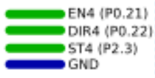
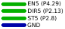
The physical pins on the board, and where they’re supposed to connect. The documentation is TERRIBLE. That information doesn’t exist. At least not publicly.
Upon consulting the manufacturer, here are the pin description for the E-axis.
delta_step_pin 2.3 # Pin for delta stepper step signal
delta_dir_pin 0.0 # Pin for delta stepper direction
delta_en_pin 0.1 # Pin for delta enable
But that didn’t work in delta or gamma to affect the stepper motor from Z in LB.