I tried a test burn today using the EleksCAM software. I notice the motors move differently than before, smoother in a way. I believe my X axis left/right is swapped as well. I tried to engrave “test” on some wood and it did it backwards. I am also noticing the laser power seems weaker than before. For the project I am working on I would have the power set to 500 (50%) but it’s not even making a mark using that now. Any suggestions? Maybe with this different version I’ll need to teak some of the settings?
I tried using this version (0.8) from below: but no luck so I reverted back to the one provided above.
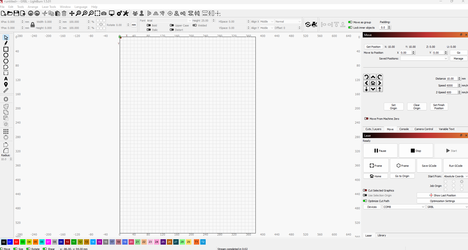
My mistake, the jogging is working fine in Lightburn. Maybe it’s the stupid EleksMaker software. Below is a screenshot. I have the origin in top left and jogging is correct.
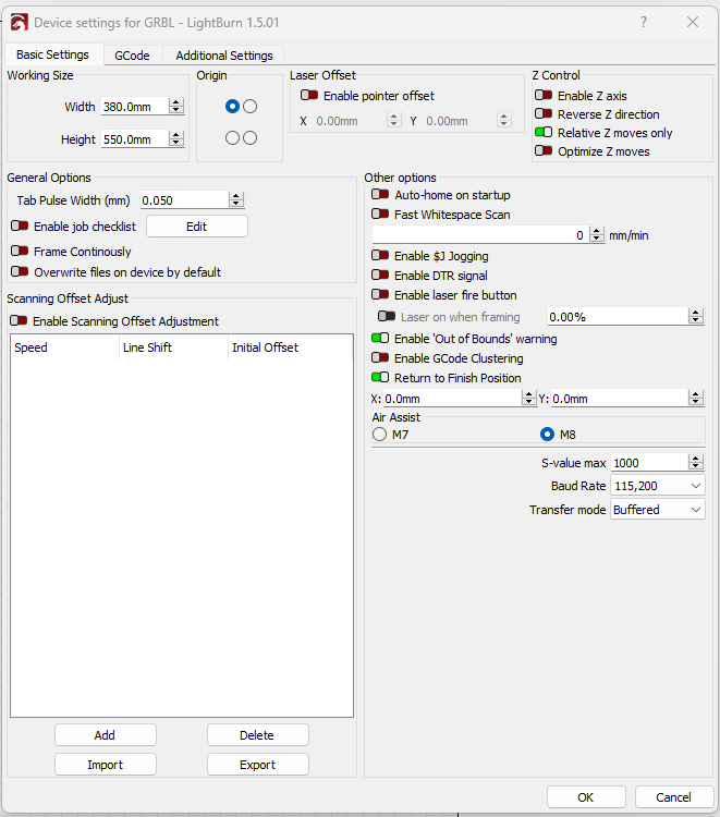
What is the value of S Value Max in Edit->Device Settings? If it’s not set to 1000, change it to that. That will likely resolve the power control issue.
Origin at top-left would be somewhat unusual for your machine.
I’m wondering if you’re perceiving the machine in the expected orientation. I’m not certain but I believe the expected orientation of the machine is with the controller at the back of the machine. Is this how you’re looking at it?
I suspect your machine is oriented 180 degrees rotated from expected mode of operation.
Also, it’s likely that your machine is intended to have origin at bottom-left.
Does position increment as you move right and down? If so, then you’re probably fine operating the machine this way if you like.
If S Value Max is set to 1000 and $30=1000 then power is most likely working as it should. If you have a meter, test the PWM voltage coming from the machine. Voltage should scale linearly from 0-5V when going from 0-100% power.
Thank you. I changed $32 to equal 1 in the IDE. What does it do in simple terms? I’ve been referencing the site below to understand the settings more. Is this an accurate reading for my version? Not sure exactly what it’s saying about $32.
As for my origin, if I use the move controls is does move as intended based on the current location. I’m willing to adjust things if it makes it easier or operate as it’s intended to.
I only have a trial of Lightburn but I’ll try a test with it. I have no experience using it but I’m sure I’ll figure it out as I go.
I appreciate the help with all this. I’m 75% done with the engraving for a wood project and anxious to get it completed.
$32=1 sets laser mode. Basically it allows for near instantaneous changes to power while in motion. In practical terms, this allows for use of M4 command that allows for variable power mode.
Are the reported positions also correct?
Start the machine with the laser head at top-left. Then try running these commands in Console and return the output:
G0 X20Y20
?
Please return the results. Also, confirm that the laser head moved diagonally down and to the right.
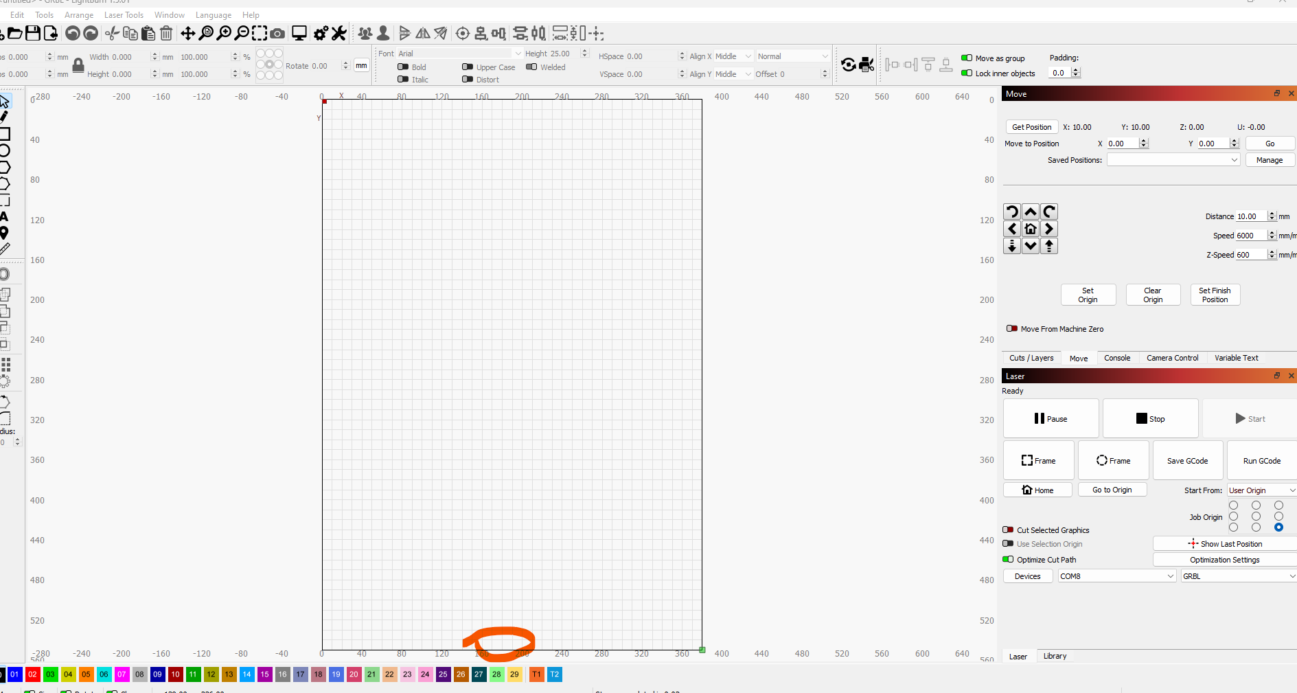
It did not move like it was supposed to, it grinded in both directions, so I assume my origin needs to change? If it helps, here is a picture of what it is right now.
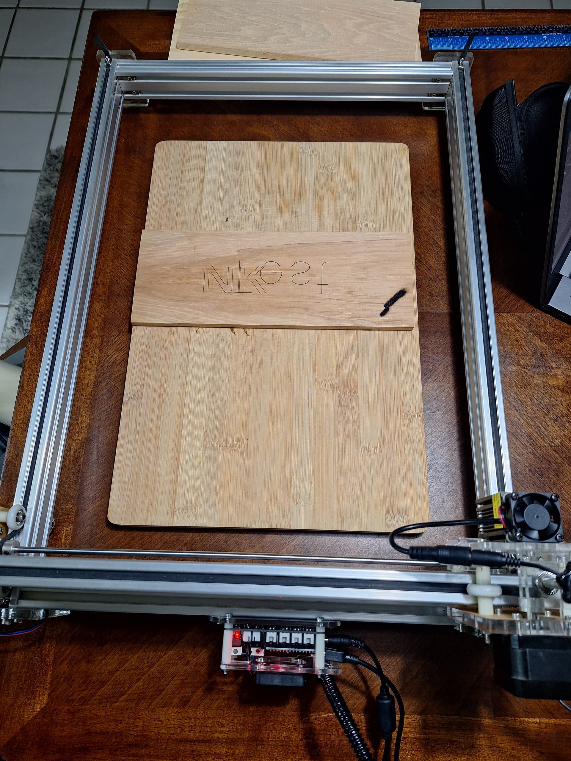
Also, the NK was performed in the correct orientation in Lightburn. I had to really slow things down and put the power to 100 to make it burn and even then it’s light and there are some trouble spots. I’m just used to the other software so there’s a learning curve.
Sorry, I messed that up. I shut everything off and disconnected it from my computer. I then manually moved the laser to the top left (opposite of what is pictured in my previous post). I ran the code in console and it did move down and to the right. Below is the console output:
This looks fine along with your description of the motion.
I’d highly suggest using Absolute Coords as the Start From mode in Laser window. Always start the machine with the laser head at top-left. Never move the laser head by hand. Use jogging controls exclusively.
Depending on the rated power of your laser the mark you’re getting at 500 mm/min at 100% power may or may not be what would be expected. Make sure the optics are clean and run a material test. That will give you a better idea of the performance you’re getting.
Good morning. I also have this engraving machine and it worked well with its software and firmware. LB had problems driving the board (I couldn’t set the power variation, the parameters $30, $31, $32 were not there in this version of GRBL). So I got a new board and now it works. for the shifting: have you tried swapping the connection on the motors board? if with the cables swapped the problem continues on the motor that was working before it is a problem with the board and not with the cable or the motor, otherwise a problem with the motor or cable. Another thing, on that card I had the GRBL 0.9 version and LB has the possibility to choose a version for this firmware. Never use eleksmaker and LB in the same session: if you use one program afterwards, don’t use the other: if you want to do this restarts your PC.
Let me know
I haven’t messed with it in a couple days. Had to set it aside, it was frustrating me too much! I know the ElekCAM software is not the best, but I’ve become familiar and comfortable with it. It does exactly what I need and I just wish I could get everything back to the way it was. I’m sure there’s a way, I’m just not extremely familiar with GRBL, adjusting the settings, and the details surrounding my setup.
The motors work fine. I’ve swapped the cables and they both work, just not like they used to. After flashing the firmware that @berainlb provided earlier I can tell things operate a little differently. They seem to work fine in LB, I could probably manage somehow after messing with it for a while, but things get funky in EleksCAM. I did not know that about the two, but good to know.
I have a new board on the way, but not sure if it’s going to be loaded with the firmware I need or if I’ll be in the same place I am in now.
If you are able to provide any info/files on what your machine is currently using it would be appreciated. I’ve tried different versions of GRBL with Arduino IDE, hex files in the ElekMaker folder, no luck so far.
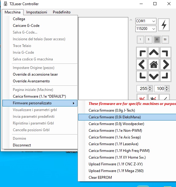
Good morning. to restore the initial configuration you can use T2laser which has firmware inside ready to flash: what you see in the image was exactly what I had, image attached. Once this is done, check whether the machine works as before: if it still doesn’t, try it on another computer, it could be that this one has dirty registers and is creating problems. Let me know, let’s take next steps. Good day.
I installed T2Laser and tried those firmware versions but the issue continues and is happening in T2, EleksCAM, and LB. I verified the version is correct using Arduino IDE.
If I use the arrows to move the laser around, the up and down arrows move the laser only in one direction along one axis. It will not go both directions. If I use the left and right arrows the laser does not move at all. I have swapped the cables at the board and that causes the same issue only on the other axis. So my motors are good, just something funky going on with the firmware I suppose. I tried the other firmware versions as well but no luck yet.
I messed with it a bit more and it seems the LaserAxe firmware in T2 (version 1.1f) is working the best so far. The laser directional controls are back to normal (although the movement of the laser is a little different as far as speed and smoothness). I believe this is the same version @berainlb provided earlier. It works, but there are a few issues still:
in EleksCAM, I can hit the preview button and it will move the laser around the border of where the burn will take place. Before, during the preview, the laser would be turned on but very faintly so that I can track where the border is of my burn. Right now it will not turn on the laser on, even if I change the settings for the laser in EleksCAM under the “weak” mode.
my test burn was done mirrored/reversed. I tried to burn “Sevan” but it was done backwards like “naveS” but also mirrored, so the letters are in reverse orientation.
it seems the dimensions are off as well. The test burn was set for 100mm wide and 22.57mm tall. The final burn was about 80mm wide and 17mm tall
Thanks for everyone’s help on this. Seems we’re making progress.
Current settings according to T2
Connected COM2 115200
Grbl 1.1f Ready
$0=10 Step pulse, microseconds (10)
$1=25 Step idle delay, milliseconds (25)
$2=0 Step port invert, mask (0)
$3=0 Direction port invert, mask (0)
$4=0 Step enable invert, boolean (0)
$5=0 Limit pins invert, boolean (0)
$6=0 Probe pin invert, boolean (0)
$10=1 Status report, mask (1)
$11=0.010 Junction deviation, mm (0.020)
$12=0.002 Arc tolerance, mm (0.020)
$13=0 Report inches, boolean (0)
$20=0 Soft limits, boolean (0)
$21=0 Hard limits, boolean (0)
$22=0 Homing cycle, boolean (0)
$23=0 Homing dir invert, mask (0)
$24=100.000 Homing feed, mm/min (100.000)
$25=1000.000 Homing seek, mm/min (1000.000)
$26=250 Homing debounce, milliseconds (250)
$27=1.000 Homing pull-off, mm (1.000)
$30=255 Max spindle speed, RPM (255)
$31=0 Min spindle speed, RPM (0)
$32=1 Laser mode, boolean (1)
$100=80.000 X steps/mm (80.000)
$101=80.000 Y steps/mm (80.000)
$102=80.000 Z steps/mm (80.000)
$110=4000.000 X Max rate, mm/min (5000.000)
$111=4000.000 Y Max rate, mm/min (5000.000)
$112=6000.000 Z Max rate, mm/min (5000.000)
$120=800.000 X Acceleration, mm/sec^2 (800.000)
$121=800.000 Y Acceleration, mm/sec^2 (800.000)
$122=5000.000 Z Acceleration, mm/sec^2 (5000.000)
$130=400.000 X Max travel, mm (400)
$131=300.000 Y Max travel, mm (300)
$132=200.000 Z Max travel, mm (200)