The laser module firmware in the Creality Ender 3 S1 Pro does not seem to support the commands required for LightBurn to successfully engrave and cut. Primarily the laser power and on/off function does not correspond to standard GRBL behavior.
I am running v2.0.8.24F4 on the controllers and screen version 1.0.2.
I tried upgrading to LightBurn v1.2.04 with the same results.
LaserGRBL works a bit better as far as printing, but the generated GCODE syntax for burning is quite a bit different.
For example, it seems the laser enable/disable is not explicit enough and the Sxxx laser power on the G1 commands is missing on nearly all of the text for the LaserTools->Material-Test for example.
Not really, but I have tried Marlin and all three GRBL profiles. None was actually successful.
They would move the laser around for the most part, but did not seem to control the laser correctly. Sometimes the laser would stay on during the traversal moves for example. Other times it would start the burn, finish only the first letter, the capital “I” in the word Interval and then stop engaging the laser for the rest of the layout even though it would go through the motions. With the safety glasses on or by watching through the lens or the LEDs on top you can tell when the laser is trying to cut and when it not.
I am a CNC novice to be sure but GCode for a laser seems pretty straightforward to me anyway so long as the controller supports the commands in a way that is understood.
There are quite a few commands that are not responded to when LightBurn is talking to the controller by watching the debug log and the console. Since this is my first laser CNC, and LaserGRBL and LightBurn are both included with the Creality laser module, I assumed it mostly works correctly if I get the correct parameters configured. So far though I haven’t seen that the code generated is correct. I can manually issue the commands and get it to do what I expect, so the controller seems like it is working as designed.
I am assuming I just don’t have some settings quite correct on my side.
Creality Print works fine (thought extremely limited) and LaserGRBL sort of mostly works, but LightBurn is a more capable product and so far handles imported images/drawings much more capably than the other products…
I was also wondering if the limit switches are supposed to “limit travel” during normal operation or are they only to let the controller know where home is, if it is interested at that time. It would sure be helpful if there was ANY documentation from Creality…
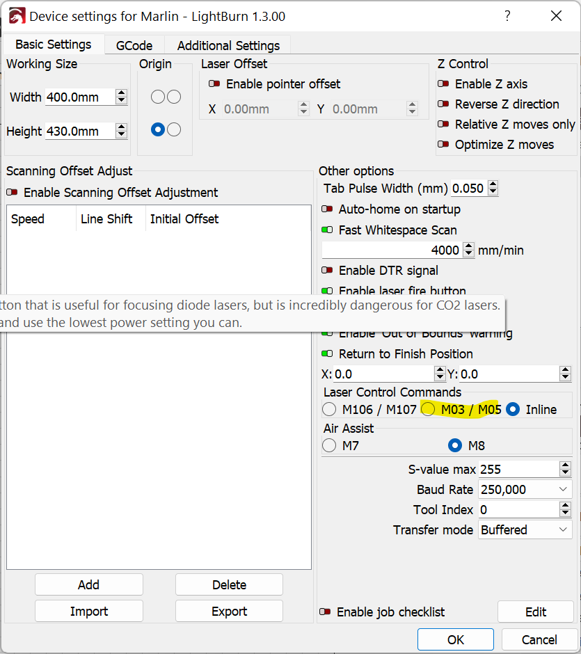
Here is a Marlin example from LightBurn. Notice how the laser/spindle is never enabled and the inline option M3 I is not specified. Only if I put the “M3 I” in the Startup GCode for the laser, does the engraving actually start.
; LightBurn 1.2.04
; Marlin device profile, absolute coords
; Bounds: X7.99 Y128 to X108.92 Y214.4
G21 ; millimeters
G90 ; Absolute coordinates
; Cut @ 25 mm/sec, 100% power ;;; How is this specified anywhere except the first G1 line?
M8 ; Turn on air assist
M05 ; Laser off if it is M5, or Stop if is is M0… ?? Unclear
G0 X69.217 Y128.659 F6000
; Layer Labels
G1 Y128.774 F1500 I S1000 ; First time power is specified, but the laser is not on. (M3 I)
G1 X69.255 Y128.885
G1 X69.342 Y129.062
G1 X69.469 Y129.237
G1 X69.649 Y129.424
G1 X69.894 Y129.638
G1 X70.093 Y129.806
G1 X70.256 Y129.955
G1 X70.384 Y130.086
G1 X70.478 Y130.199
G1 X70.592 Y130.4
G1 X70.63 Y130.59
G1 Y130.683
I think I misunderstood you the first time. You were correct, I did have the Inline enabled as I had your suggestion flipped in my head that you wanted me to enable it and NOT use M3/M5. When I tried the M3/M5 before, I thought it was not disabling the laser between engrave points and the transversal lines were being engraved as well, but that could have been the GRBL profile doing that instead of the Marlin.
I will go test more though now and see if there is a combination I overlooked like you are suggesting. I did not think it was going to be quite so picky and I so I did not thoroughly document each attempt when I went through with each result for the four profiles. My bad.
Marlin, specifically, has way more variations so is rather picky about your particular configuration. GRBL tends to be quite standardized which is nice.
Incidentally, inline would be preferable if your firmware is configured and compiled for it. However, I don’t think I’ve ever heard of this being done by default on any system.
I started the testing and trying other things as you described and it was somewhat better. The laser seemed to have a very limited dynamic range of effects on cardboard and wood samples. I am not sure yet what is normal though until I learn more and get more experience.
I eventually ran into a snag in that the laser module stopped lasing completely…
The red power light on the module still comes on and yet no laser light ever appears. Even the blue LEDs that indicated the PWM/blue laser diode activity on the top of the module have stopped flashing. I did normal troubleshooting things. Reset the unit to factory settings and rebooted the printer, switched the mode from Printer to Laser and back a couple of times. Checked on the cable connections, etc… Tried Creality Printer utility, LightBurn, SD-Card local GCODE playback (which used to work), etc… All the motions and movements look fine, just no laser from any software or even manual commands.
Converted back to a printer it still works fine, but not as a laser currently.
I started the slow process to contact Creality Support, so I suspect it will be at least several days before anything happens.
I managed to swap the 1.6W laser for a 5W model to test and same results. I assume this means that something between the controller and the laser failed and unless that interconnect board has active circuits, then the controller needs to be swapped now. Still waiting on Creality. All they have said so far is one sentences to send them videos of the failure and that single sentence took an entire week to get.
Have you checked voltages coming from controller to see if PWM is working correctly? Voltage should read roughly 0V when at 0% power and increase proportionally up to 100%.
Is the 5W model made for your machine or it’s a generic model? If generic, have you made sure the wiring it correct?
Yes, this looks the case, although it looks like the specific syntax may be different from LightBurn. You could try modifying the LightBurn g-code to see if you can get this to work.
Is the “interconnect board” that you referenced something else entirely?
So is laser control strictly on/off?
I’m trying to understand how different power levels are configured. I can see varying S values in the sample gcode. And looking at it more closely I’m noticing values higher than 255 there. I had thought Marlin based setups were generally configured for 255 max.
It uses the PWM signal to modulate power, but the controller that was working stopped sending the PWM signal at all. The vendor thinks something happened to the controller board and is needing to send a replacement unit.
My apologies as you probably know all of this already.
There are three wires for the laser. PWM, (Gnd / -), (24V+)
24V +/- is hot all the time and the PWM signal (~1.5kHz rate at 3.3/5V depending on HW version) is sent to turn on the laser as needed. That function ceased to work for all recent attempts. This was for saved GCODE files, LightBurn, even with the Creality supplied utilities used for verifying the setup. I would confirm the PWM with a scope, but with no signal there currently there is not much to see.
Since this controller is a 32-bit version of Marlin, I understood that it supported 16-bit resolution for power levels, but this implementation is configured for a range of 0-1000. I am no expert here, just relaying what has been discussed around the net and what is in their config/test files I have looked at thus far.
I have been out of town so I hope to be back in town when the replacement board arrives to try again.
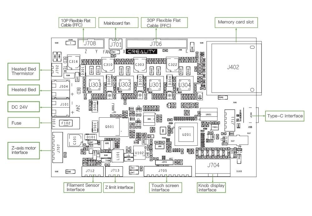
Assuming this is the correct board how do you supply 24V and PWM to the laser module?
The hardware likely can support it. I haven’t seen any clear documentation on Marlin support for wider ranges. Convention is what I think drives the 0-255 values currently though this could just be a carryover from 8-bit implementations.
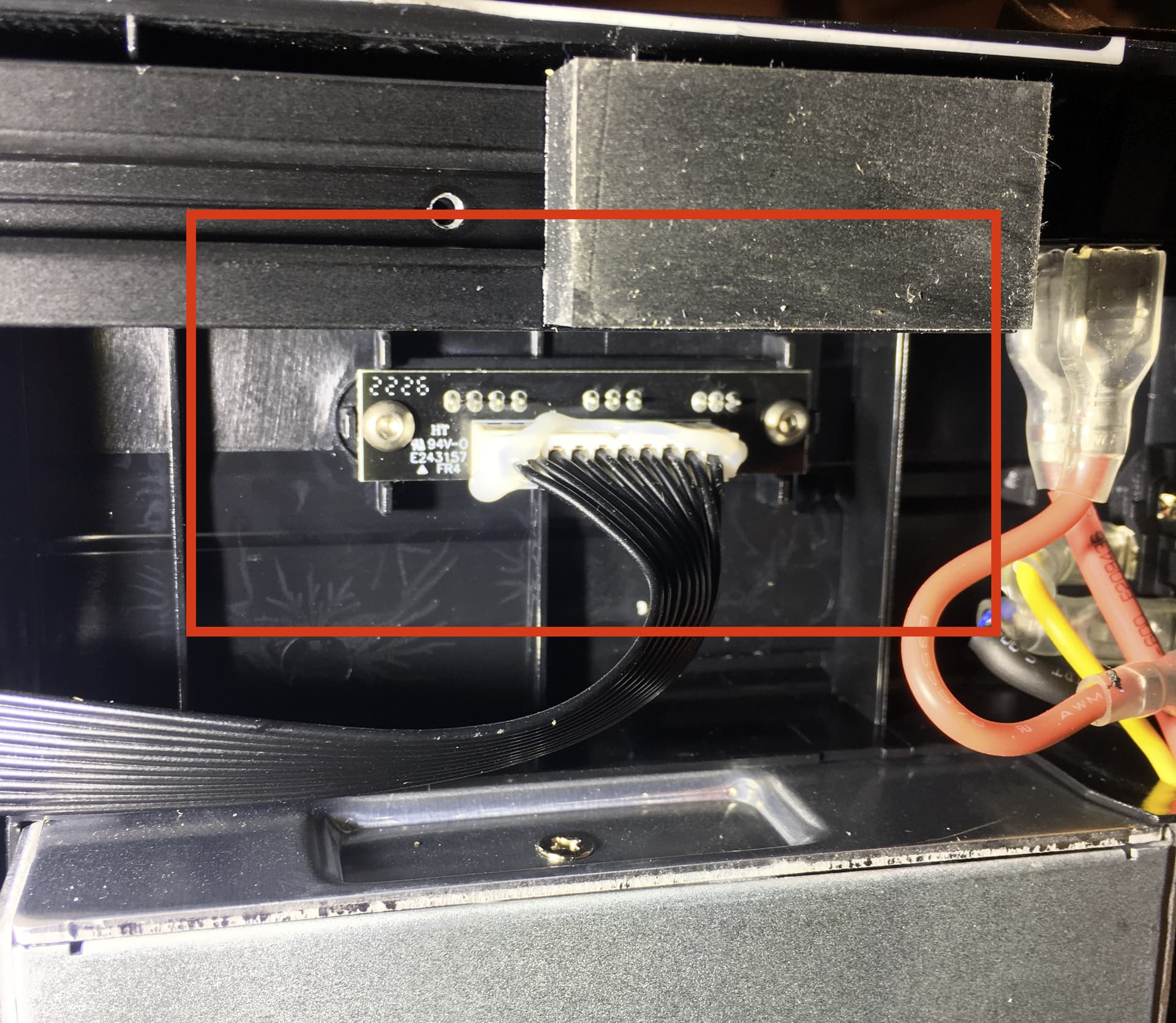
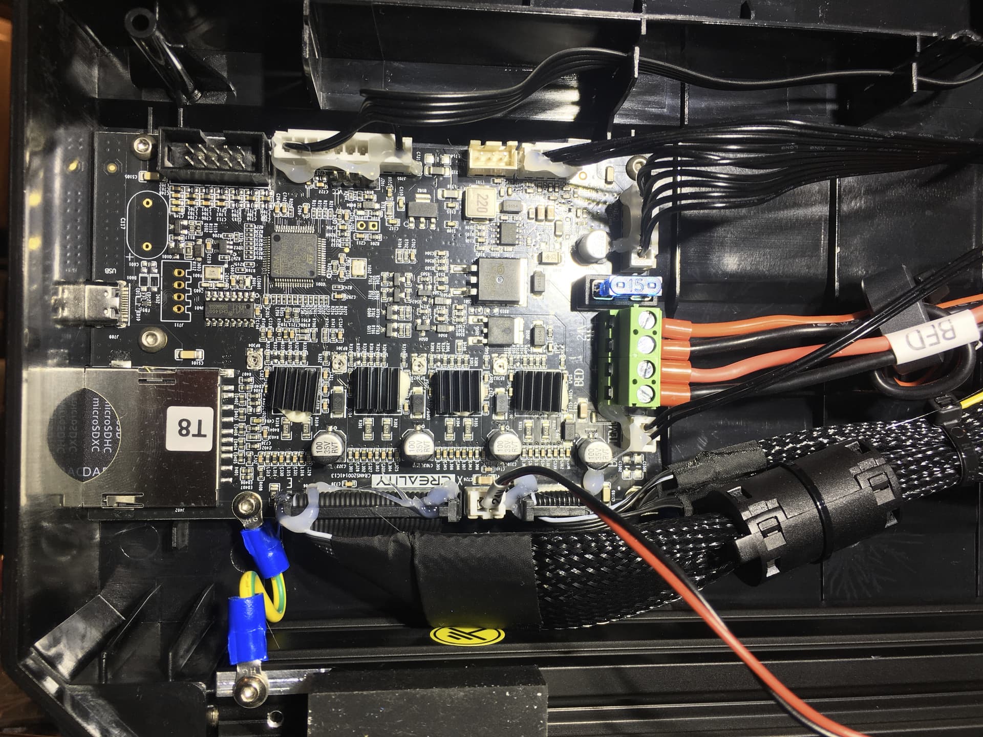
I looked at the photos I have of the board and I think that is the correct one. There is a midplane-PCB between the motherboard and the cable connections and I think probably has to be one of the ribbon cables.
Can you take a photo of what that looks like? Or if there’s a stock photo that’s fine too. I’d like to understand if it’s just a power adapter or if there’s logic on the board.
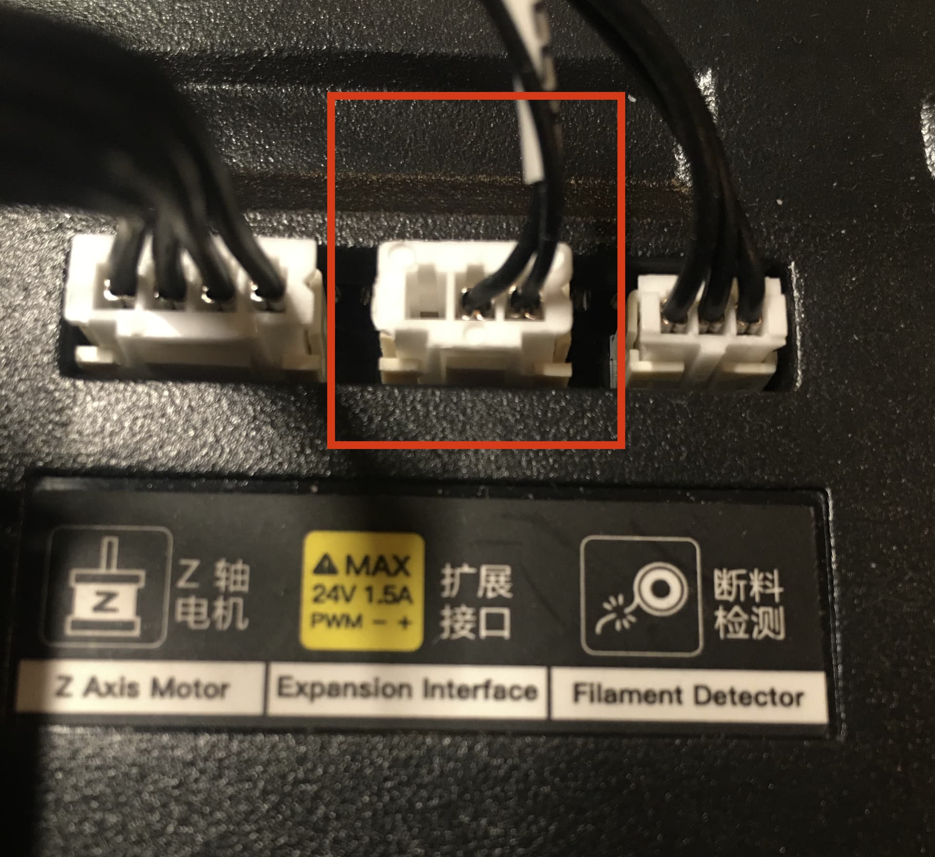
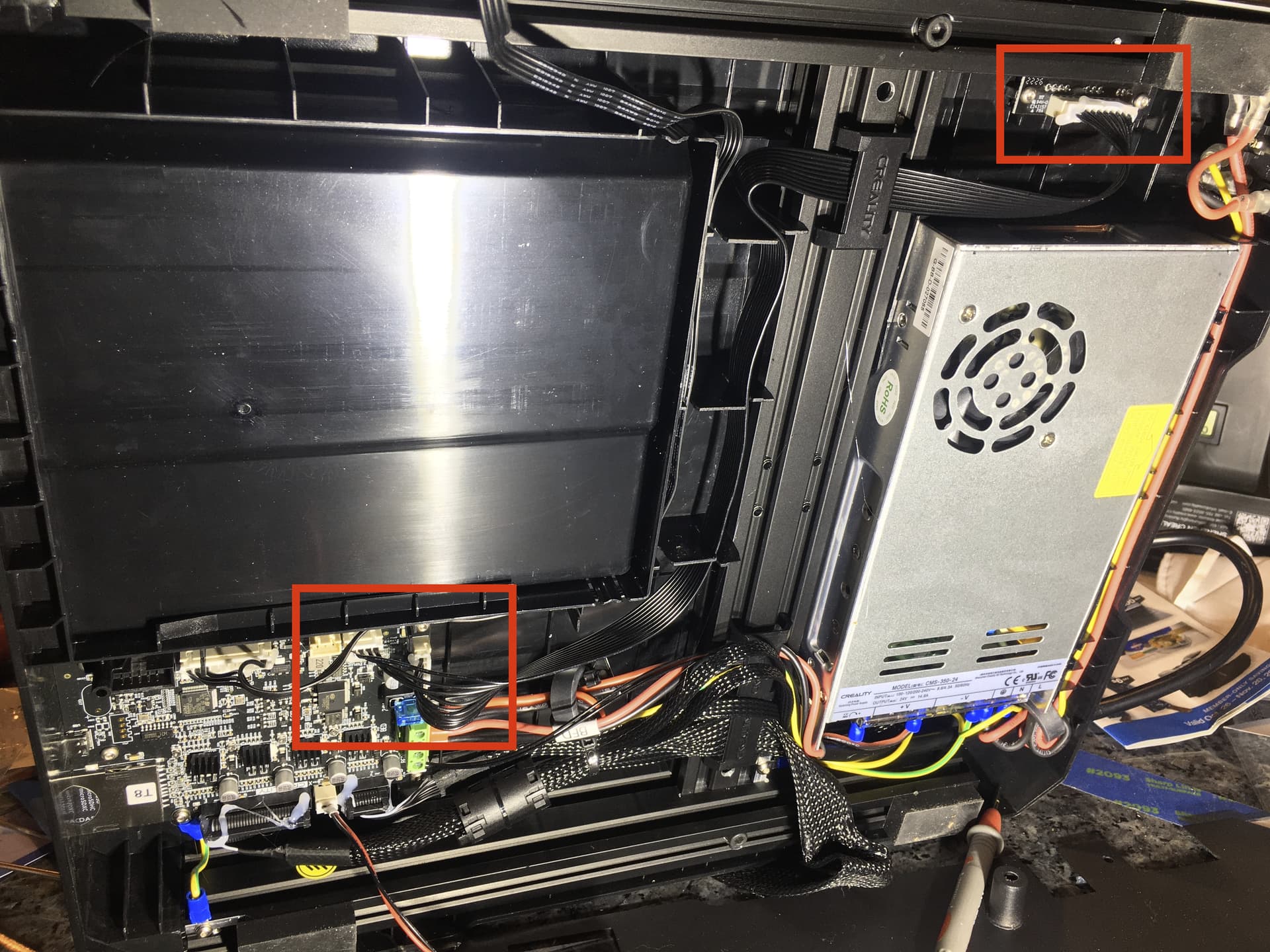
Here is what can be seen without removing the hot-glued cables or the main PCB.
This middle one is the connector used by the LED/Laser cable. LED uses 24V +/-, Laser uses that plus the PWM pin. Note that the stepper motor for Z is only using 4 pins, but the J707 connector has 6 wires and the J712 connector has 4 pins, but the filament detector connector only has 3. There are three bonus pins right there.