I am having a problem with my laser, I first noticed it when I started work on a 900mm by 1300mm piece of wood where I noticed that the engraving and the cut layer aren’t aligned properly as if there is a shift between them that makes them overlap. I have tried everything and tried other software and every-time there is a different problem. My lates trial was to run the material test of lightburn with all its default settings. Yet the result is still skewed. My machine is practically new.


The solution in this post may be your issue.
Tried that solution but unfortunately it didn’t help.
You mentioned that you had the same result with other software, correct?
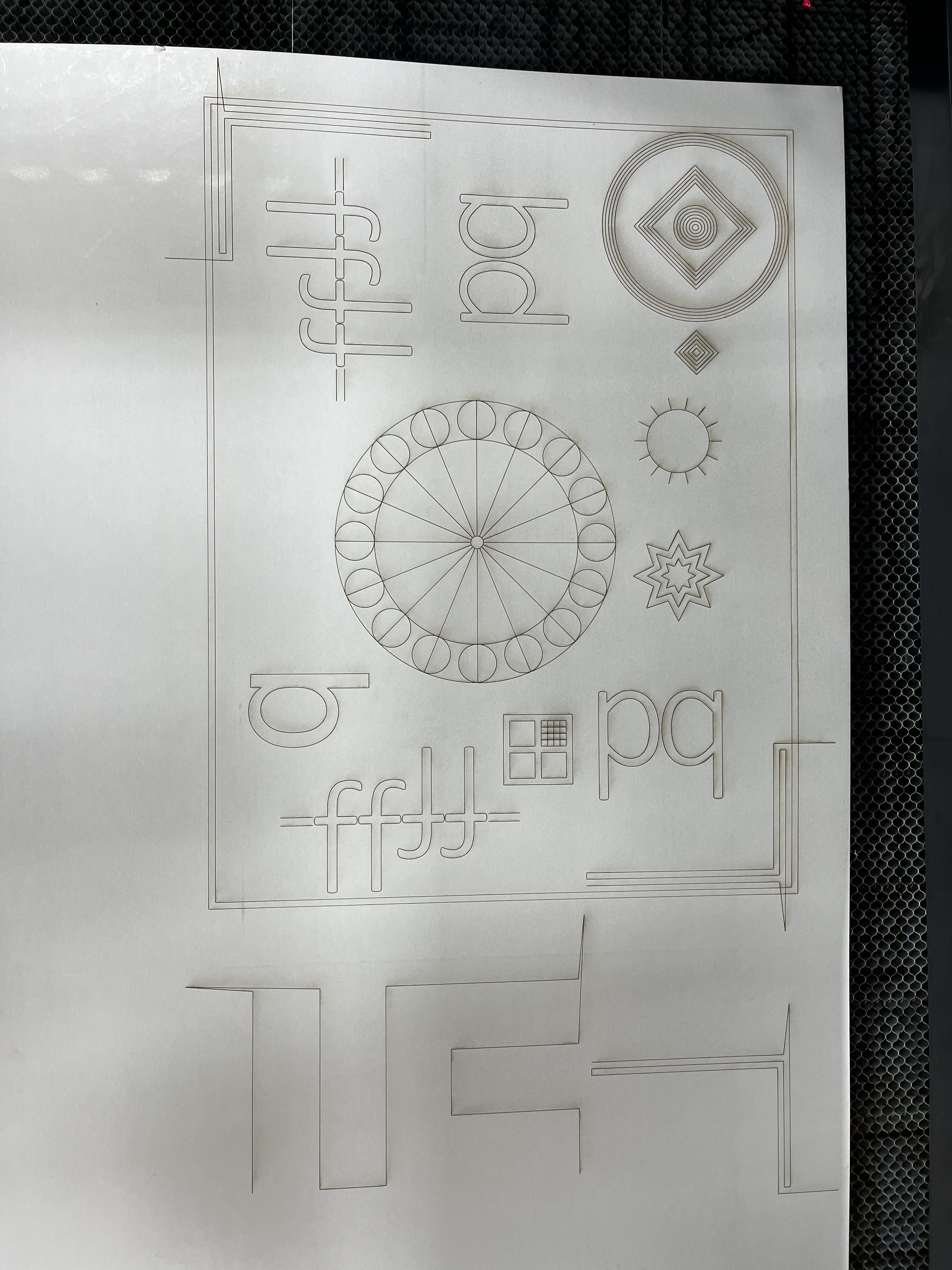
Try this, scale this file up to half your bed size or larger and run it on cardboard, at high speed, with optomization settings turned off and the power just strong enough to get a good marking on the cardboard. Post a picture of the results.
BacklashTest.lbrn2 (68.8 KB)
Both PWM Rising Edge Valid switches will typically be False. Upload screenshots of the X and Y axis settings in Edit → Machine Settings → Vendor Settings so we can look over your shoulder.

Yes, that does look good. With that info we should be able to rule out physical slipping.
Switch X PWM rising to true test.
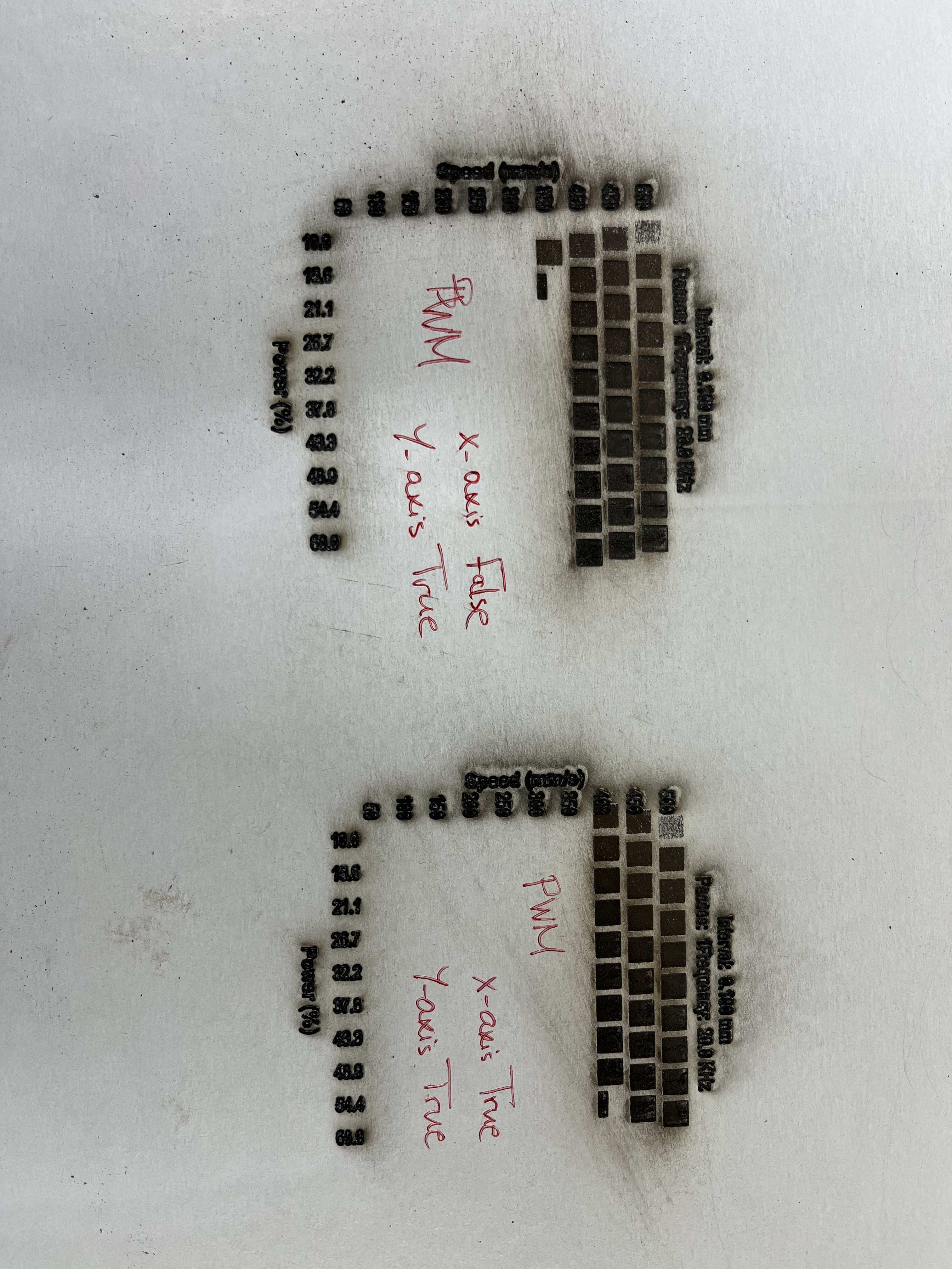
Switch X PWM rising to false and switch Y PWM rising to true test.
Switch X and Y PWM rising to true test.
The polarities look good.
The 4.8 µm step length seems unusually low for a large machine running at high speeds. The step pulse rate will exceed 100 kHz at 500 mm/s, which is close to the upper limit for most stepper motor drivers.
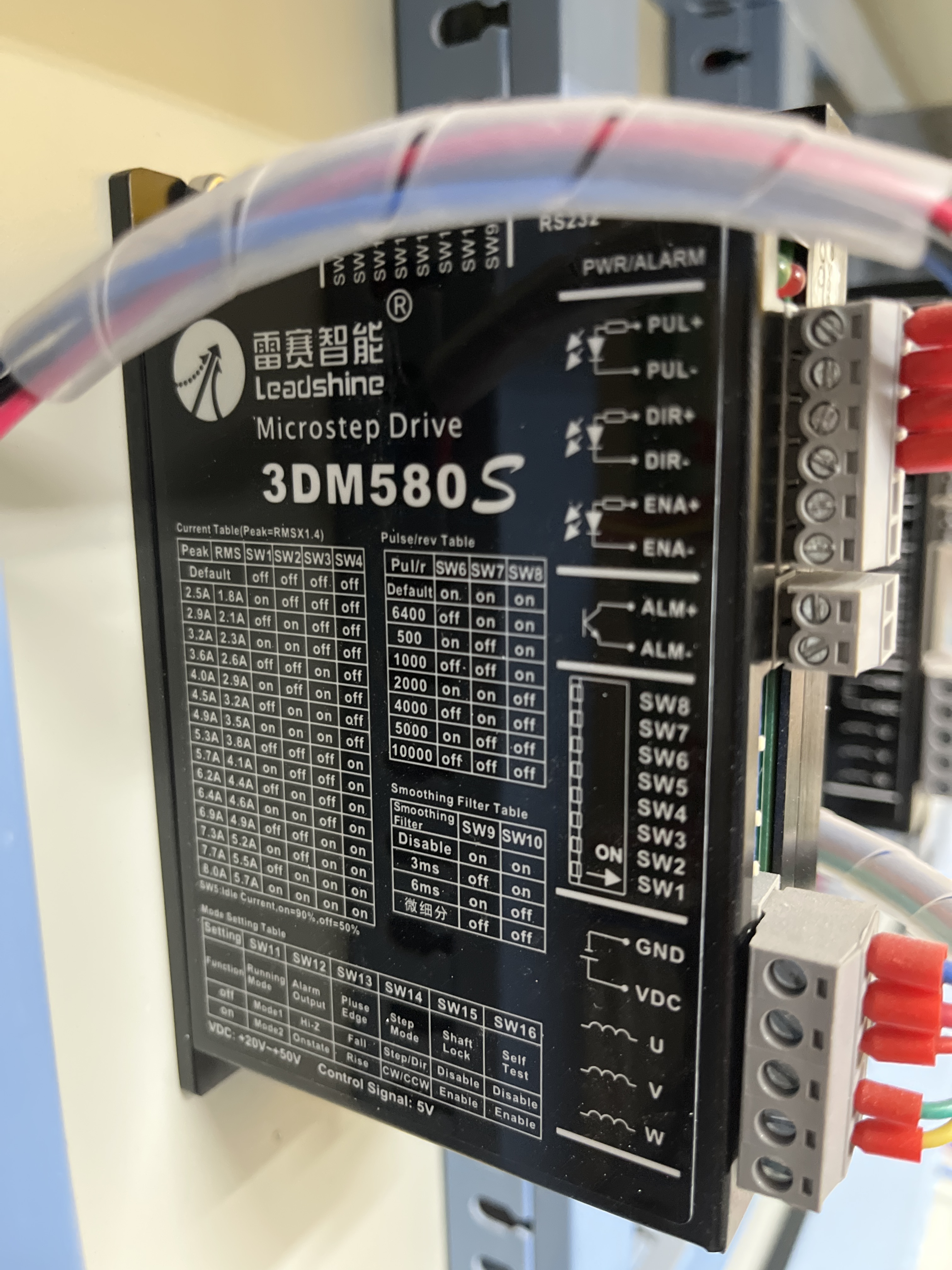
Upload pictures of the stepper drivers showing the data plate on the side and the DIP switch settings. They’re typically mounted so you can’t quite see the entire data plate, but they look like this:
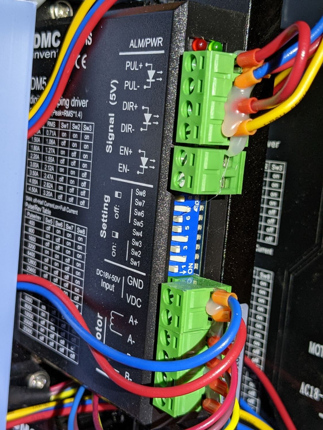
If you can read the exact stepper driver model number (which is behind the wiring in that picture), it will help track down the data sheet with the specifications.
The X axis acceleration may be too high for a large machine.
What are the X Acceleration values in the Cut Parameters and Engraving Parameters sections of Edit → Machine Settings? Screenshots may be easier than copying the numbers.
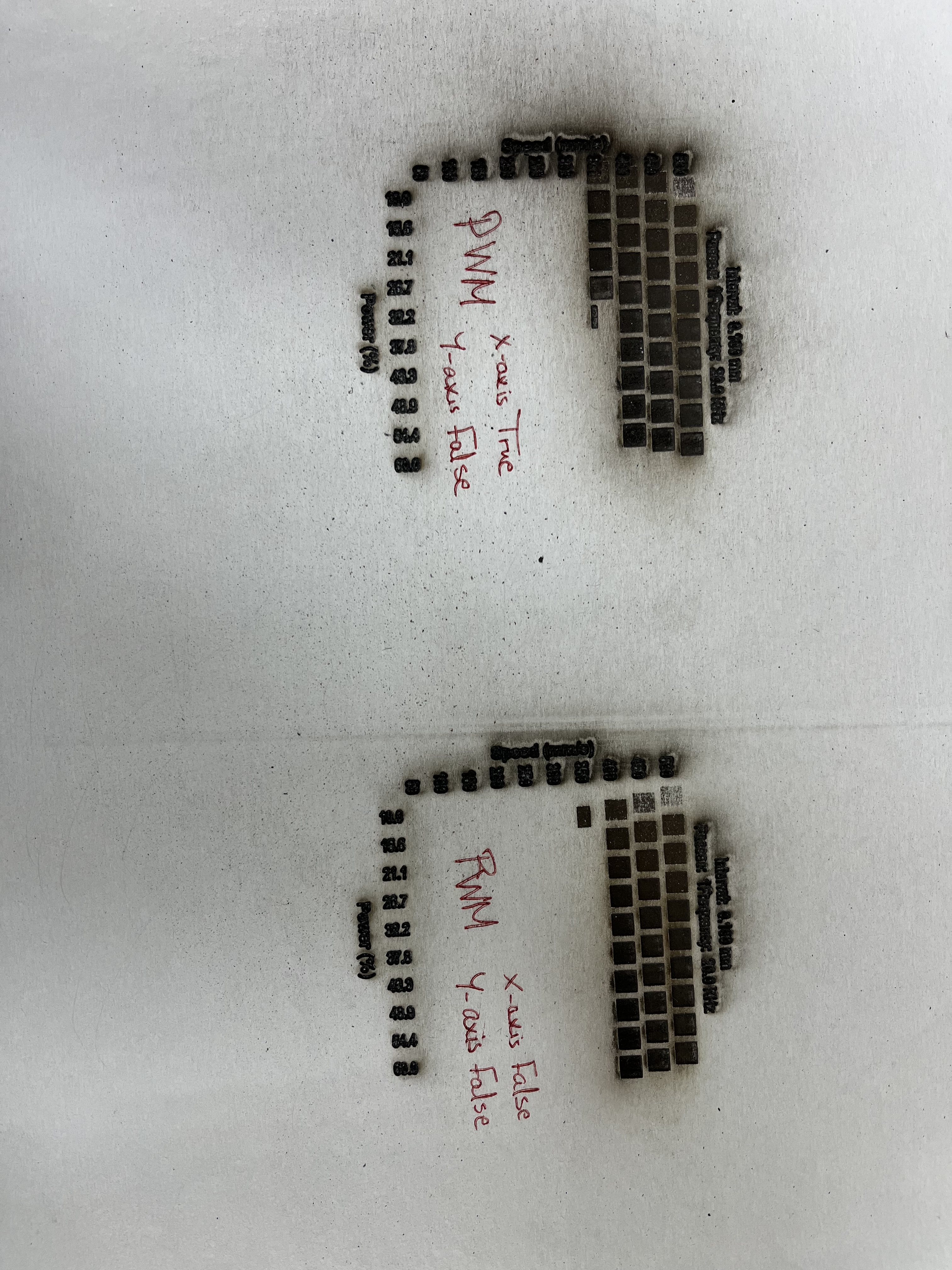


The usual setting of False for PWM Rising Edge Valid should work for both axes.
That setting seems to produce a pattern marginally better than the others.
The 3DM580S manual says it can handle step rates up to 500 kHz, so the 100 kHz called for by the step size isn’t unreasonably high.
The X axis acceleration in the Engraving Parameters section is almost certainly too high. Reduce it to 5000 mm/s², make sure both PWM Rising Edge Valid switches are set to False, and see if that improves the Material Test results.
If looks gets better, but remains skewed, try reducing it to 2500 mm/s².
You may as well reduce the maximum power in those tests to 25%, because it’s obviously far too high for the cardboard. You can also reduce the power in the text layer to the minimum required to fire the laser. That will have no effect on the speeds, but should reduce the charring.

At this point we have eliminated all the usual causes, which means careful experimentation is in order.
The 3DM580S stepper driver has several fancy configuration features that may conflict with the Ruida controller’s normal operation. The row of DIP switches along the top of the driver select these features.
For both stepper drivers:
- Disable the Smoothing Filter by setting both
SW9andSW10off. - Enable Large Torque Mode by setting
SW11on. - Verify
SW13is set off to select falling edge for theStepinput. - Verify
SW14is set off to select step-direction mode.
If they’re already set as I suggest, that rules out a few promising solutions. ![]()
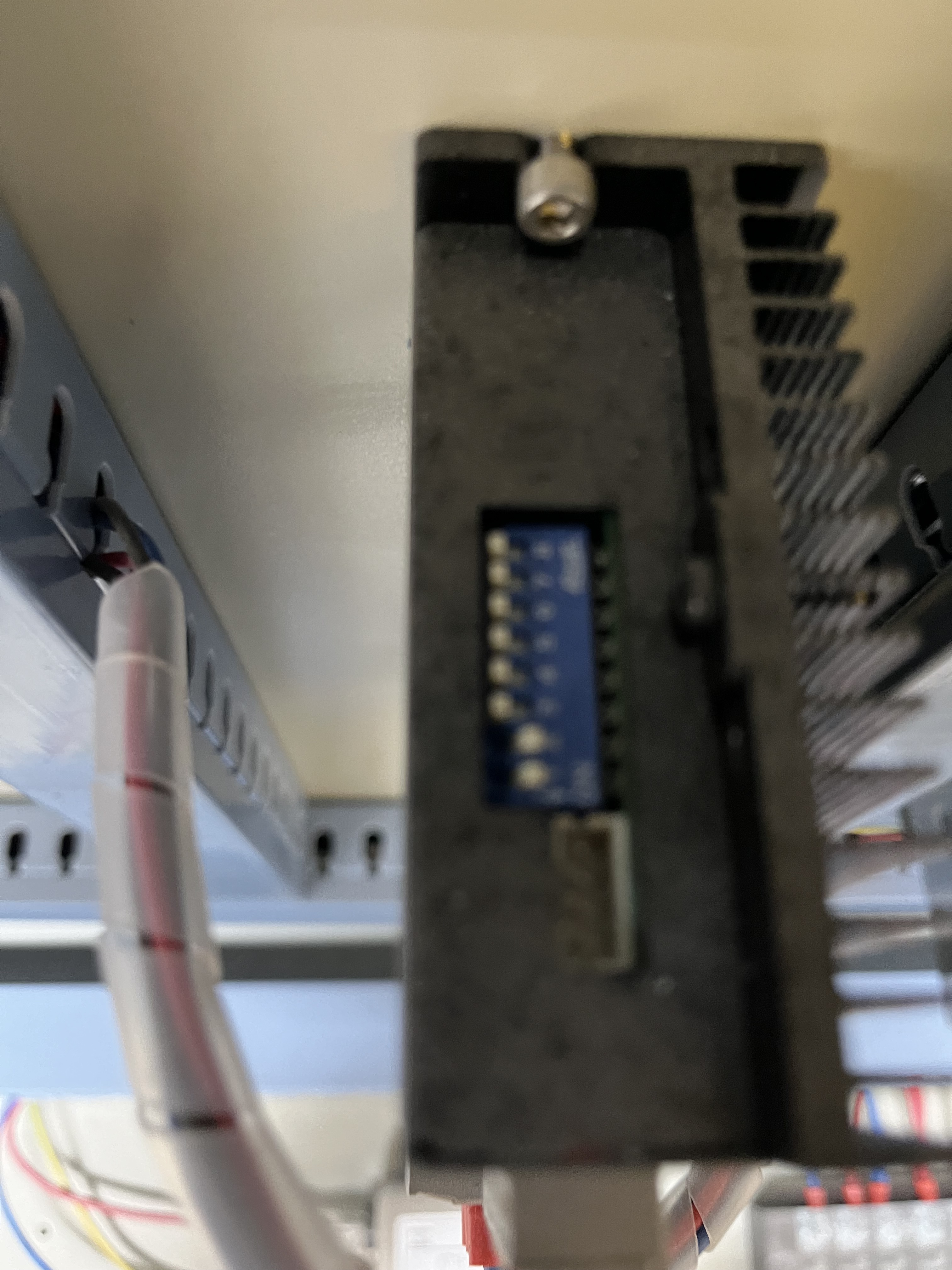
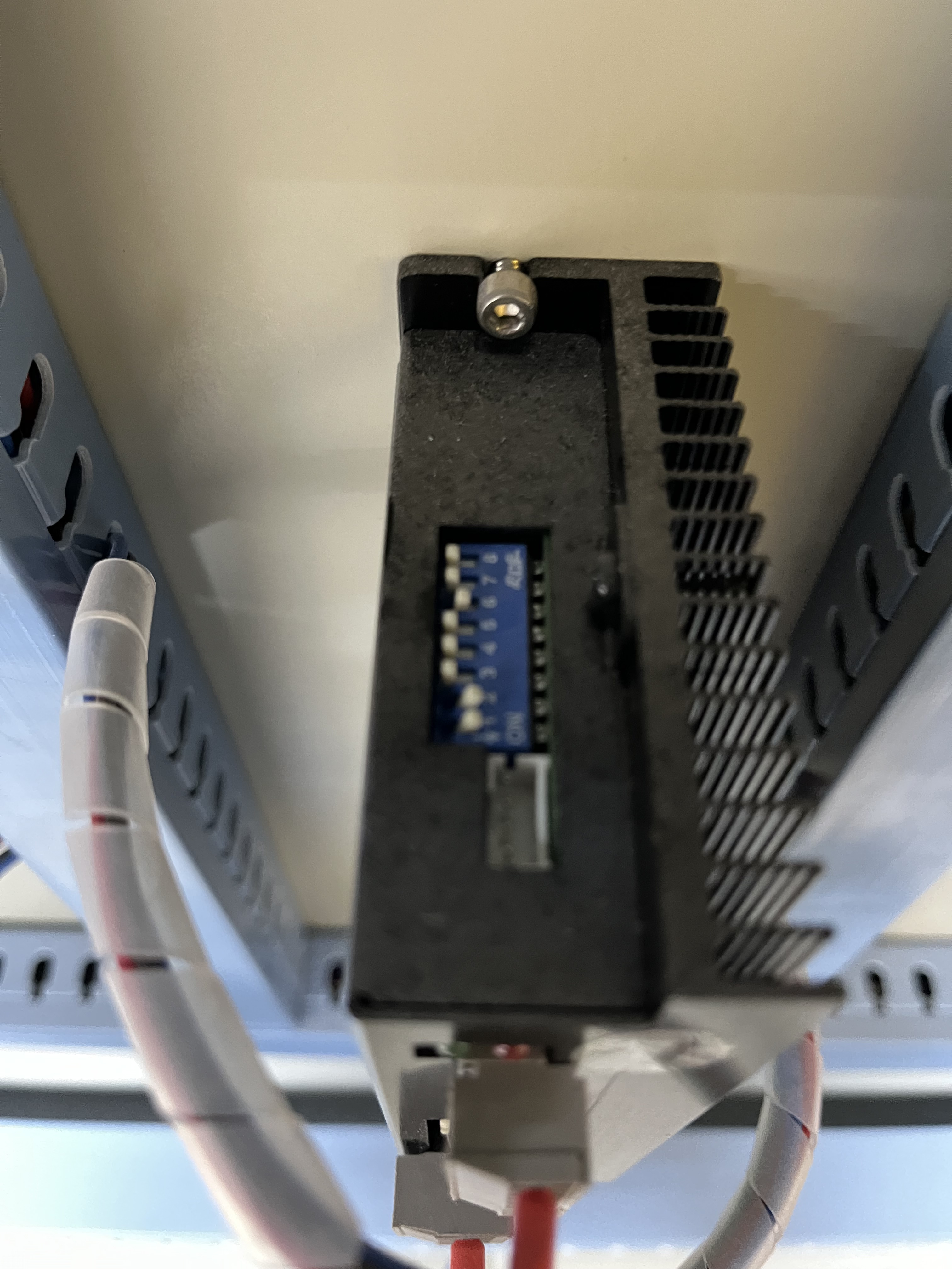
Take a picture of those switches before you change any, so we know what they were and you can restore them if needed.
Run a test after changing each setting, because it’s not clear which one (if any) will make a difference.
You may as well, as the solution seems to lie elsewhere.
Excuse my question as I am quite unfamiliar with the mechanics of the machine. Should I do this test on both Drivers or just one?
Both stepper drivers should behave the same way, so make sure they always have the same settings.
Several folks have had trouble trying to replace stepper motors with servo motors, due to their different response characteristics, and I hope the drivers in your machine were set up incorrectly. If that’s the case, making them dumber will improve things.
Perhaps somebody accidentally bumped a DIP switch, somewhere between the factory and the inside of your machine. Wouldn’t be the first time, I can assure you. ![]()

Finally it worked out, and it was the simplest thing.
It was just as you said, I had to just make sure that all the switches on both step motors are exactly the same. Apparently, It was just one switch.
And just slightly bumped!
I made a mistake in the settings for SW9 and SW10 by saying they should be set off. The photo shows they’re both on, which is correct to disable the Smoothing filter. It still seems backwards, but maybe I’m just sitting upside-down.
Setting SW11 to off selects Low Speed Mode, which seems incorrect for a laser. However, as long as the machine works, leave it off. Keep it in mind should something weird happen in the future.
I’m definitely putting another notch in my lipstick case for this one … ![]()