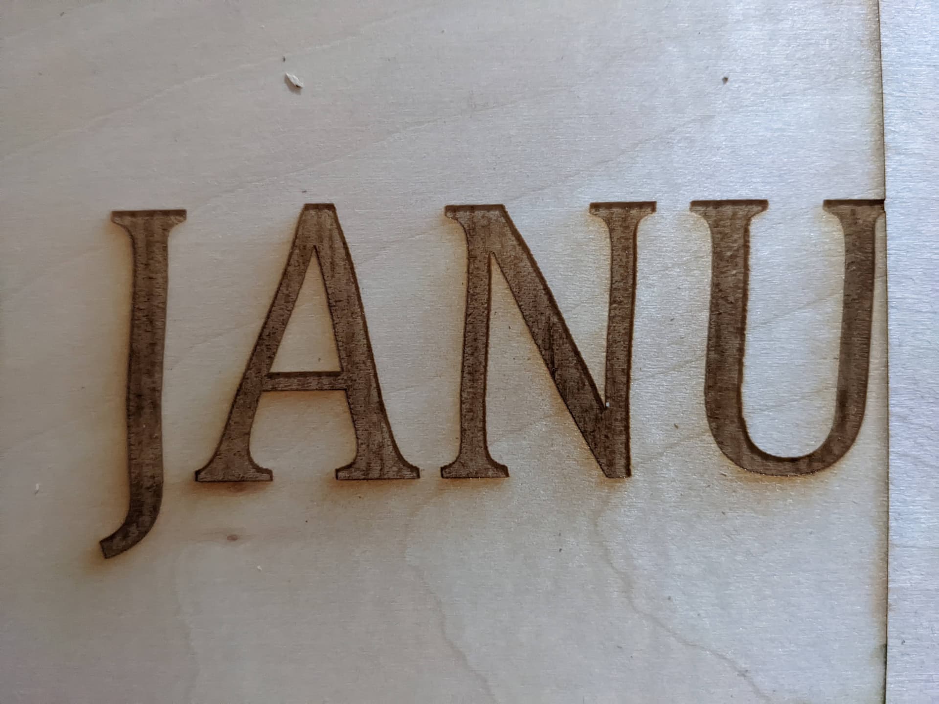
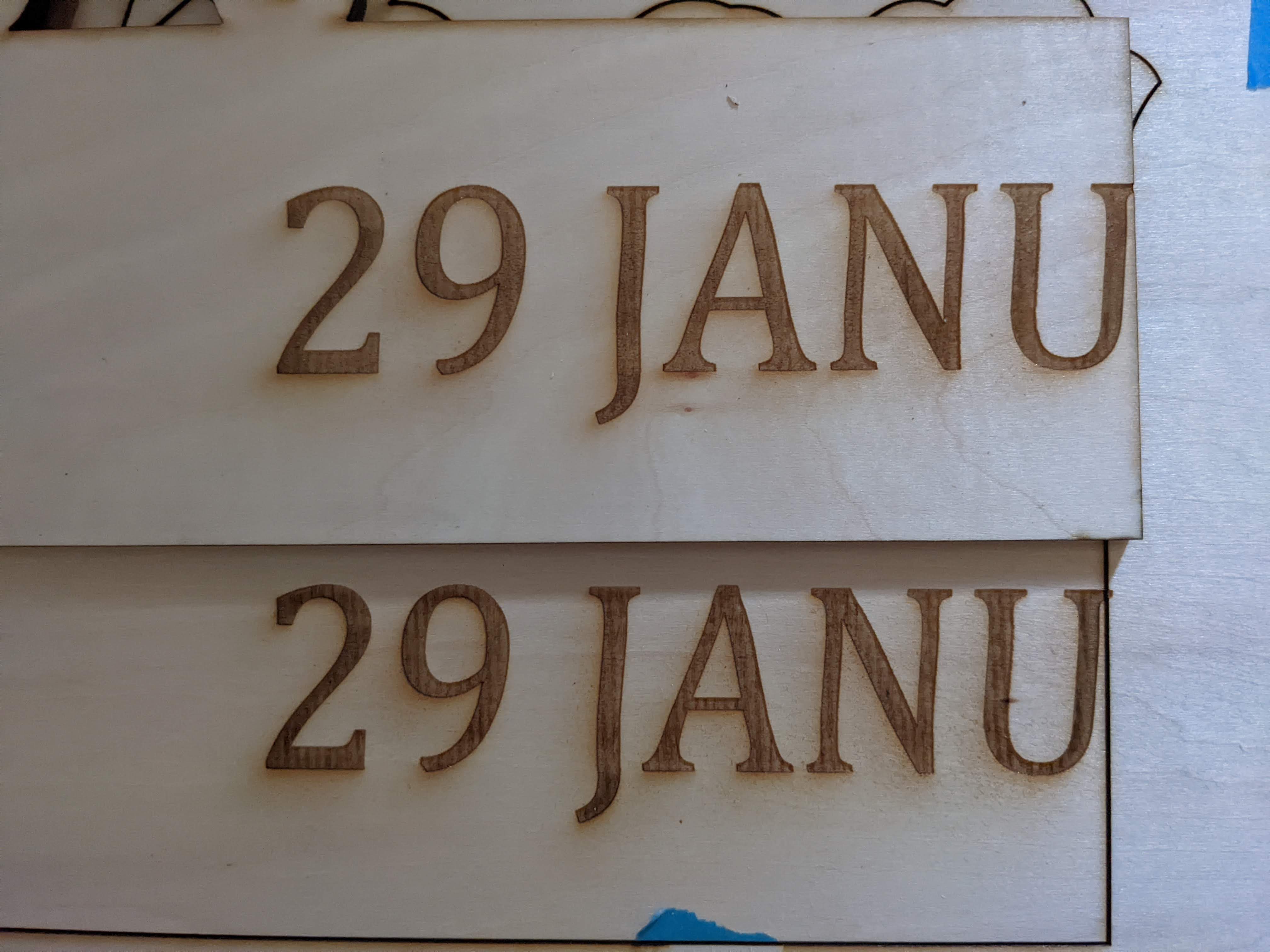
I have an engraving, which started out correctly, but mid way the engraving started slanting to the right. Initially suspecting it to be an hardware issue, I redid the engraving, which came out exactly the same.
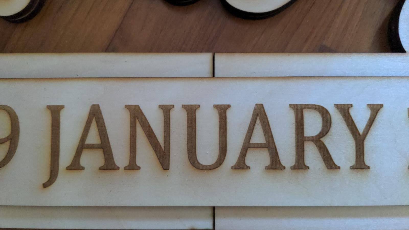
So i went to shift the location of the engraving (plus modify the cut lines not related to the engraving) as i was running out of material, and the shifting went away!
The 3rd engraving coming out right led me to think that it could potentially be a lightburn issue rather than a hardware issue.
My settings for all 3 engravings are as follows:
100mm/s, 3% power
Bi-directional fill on
line interval 0.1mm
LPI 254
Smoothieware controller (hence no access to machine settings like acceleration)
Fast whitespace Scan, Enable Smoothie Clustering are all off
Transfer mode buffered
I have searched the forums for laser shift issues and found some similar posting, but not really any resolution.
Why would the first two cut come out exactly the same and start slanting at the exact same location and at the same rate if it is mechanical in nature?
The laser i’m using doesn’t have belts. It uses a screw rod mechanism so there’s no slack to begin with. The cuts around the same area (not engraving) also came out perfectly straight, so there’s no binding and no gap for the machine.
The fact that it came out differently in different locations to me indicates a hardware issue rather than software. From a code perspective the objects would have the same code, just offset. If it was instructing the laser to make wavy lines it would have done so consistently.
I wasn’t initially thinking belt slack. I was thinking binding. But if you’re using a screw then possibly something else.
What types of screw rod is this? Threaded rod or acme or something else?
What is the mechanical setup for X and Y?
This is a good question. But if the fault is along the X-axis then you could have a single line cut straight but still show waviness or variation between lines along the X-axis.
My guess right now is that the Y-axis threaded rod is either not straight or there is some sort of variance creating lateral wobble that’s showing up on the X-axis lines. Or, the threads are fine but whatever you have set up to track travel (wheels?) is wobbling or loose at that point.
Focus on the Y-axis portion where the worst wobbling occurs.
An additional idea. You could create a design of grid lines, both vertical and horizontal at regular intervals. Burn that and see if you can identify variations at different points along your bed. My guess right now is that it should reveal problem spots where items are not tracking square.
For engraving lines in a grid, no lines appear to be slanted. this problem only appears when trying to do fill for the particular text in that particular instance.
I agree with this! that’s why the first two cuts came out exactly the same, with both “wavy lines” cutting twice consistently. The first two cuts pointed me to an software issue, rather than a mechanical issue that could manifest itself so accurately and precisely twice in a row.
Not sure what other types there are, but there’s threaded roads and also smooth rods for both x and y axis.
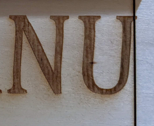
Yep, but the cuts also Y-axis appears totally fine… can refer to the cut line in the first picture, right beside the letter “U”.
there’s no wheels in the setup, only linear bearings as far as i can see.
By the way, it’s not really a wobble from what i can tell, more like each subsequent engraving line is somehow being offset by a very small amount to the right for each pass, both in the forward scan and return scan, up to a certain point, before it returns to being straight…
By the way, just sharing one more engraving done at the almost the same Y-axis height as the pictures in the original posts, without the slanted phenomenal. So kind of rules out hardware issue for me…
The code generated would be the same with just an offset so it can’t be the raw instructions that are incorrect. I would have to be something in how those instructions are being executed. Normally having the same pattern show up would be an indication of a regular inconsistency in the hardware that’s repeatable.
I see this more clearly now. Trying to think if there’s a scenario that explains this.
Okay. I’m going to assume for the time being that the axes are travelling straight.
This again reinforced the Ruida problem. That’s caused by a difference in detection of motor movement in leading or falling PWM signal for laser firing. It’s possible this could be similar but hard to say. So instead of this being a mechanical issue this could be an electro-mechanical issue.
The one other possibility I’m thinking it might be is from backlash in the system. You could test this by running some circle tests. Maybe try both clockwise and counter-clockwise circles and see if they come out round and meeting at the ends of the cut.
Is there other software that can be used to drive the laser? Might be a good test to see how the other software performs to eliminate it from investigation.
I feel like I can see a slant on the vertical lines in the P and H. Hard to say. Also the / in 2/3 doesn’t look quite straight. The engraving in the lower portion seems good though. The raised letting is a nice effect.
Again, unlikely but try to test it. Some possible tests:
try a different port/cable to see if that affects performance
try maybe using synchronous mode
save g-code and run in a different program
run a similar engraving operation with a different program - I know laserGRBL has some preliminary smoothieware support. Might work. Not sure if your laser comes with its own software.