Hi everyone,
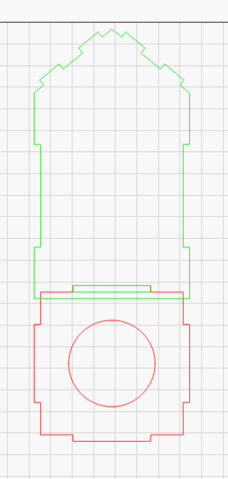
having issues with some designs bought on Etsy. It’s a set of houses and the cuts are very loose. I read thru some threads and watched some videos about kerf but I might still need some help. I attached a lbrn file for reference, my cut layer has the kerf offset set to 0.
I tried some kerf tests following Rich from lahobbyguy and measured my kerf at around 0.100mm. But if I now would set the cut layer with that kerf I assume the parts would be even more loose as they are now. Am I right? Should I inward the kerf or what? Thanks for any help.
Okay. I think there may be a couple of things going on:
As you suspected, kerf is a likely factor in this.
The parts themselves have gaps in the design. Check out this example where the tab doesn’t quite line up with the slot. This doesn’t seem significant but when you’re chasing a very specific fit these things can add up.
Kerf works in two directions. For outside cuts you want to cut larger as to account for kerf. For inside cuts you want to cut smaller. If you express the kerf as a positive value it will generally do the right thing, even for inside cuts.
Note that the value you use for kerf adjustment should be half of your measured kerf. So if your confirmed kerf is .1 mm, your adjustment would be .05mm.
For your current issue, I’d suggest you modify the design to perfectly size all the components as if kerf is not accounted for. Then use kerf adjustment to manage fit.
Hm. Have reviewed it again and now I see there are some gaps between the joints. Some parts are smaller (fingers) as they should be. But some are same size and should fit. But that’s weird - the Lighburn measurement tool (the ruler) sais it’s the same lenght despite it isn’t. When I fully zoom in I see that there is a definite gap…
If I buy the some designs/files I expect them to be perfect. So are the files corrupt or it’s just as it is and that’s fine? Should I write to the seller?
Based on some of the files seen around here in recent weeks, that is a completely unwarranted assumption.
For interlocking parts, “perfect” is in the eyes of the beholder. The result depends on both the materials and the laser cutting it, but the designer has no control over either of those.
For example, if the interlocking parts were laid out for “3 mm” plywood, your 2.9 mm plywood and my 3.2 mm plywood will have completely different and equally poor fits. If, by some miracle, we both had 3.0 mm plywood, your diode laser will produce a different cut width (“kerf”) than my CO₂ laser and the parts will fit entirely differently.
Just getting design files with closed shapes and nominal sizes would go a long way toward improving the result, because then you can adjust them (perhaps with LightBurn’s new tab adjustment feature) to match your materials and laser. If that’s what you got from the seller, you are far ahead of the crowd …
Hi,
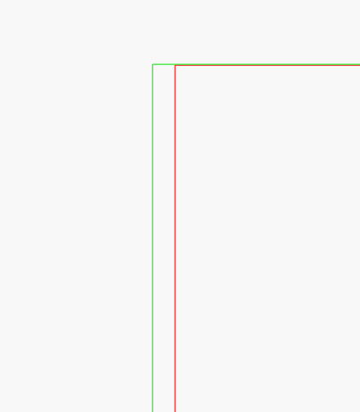
thank you for your answer. Maybe I just don’t get it. Please take a look at my attachements. These are two parts, which sholuld fit together. I separated it into two layers so it’s easier to see the details. The green one has the opening and the red one has the finger of the joint. If I center align them and zoom way in, the green line is longer, so the finger is longer as the width of the groove. Sorry for my bad spelling, hope you understand.
Yep ednisley, you’re right. I totally agree with you - all the machines are different and also the wood isn’t uniform at all. But wouldn’t it be for this very reason easier to prepare and sell the files without any kerf correction, which everyone would then do by himself regarding his material and his laser?
How did you get those kerf numbers If you don’t mind? Is it possible to somehow measure this things when I buy the files, to know at the start where I am and how to setup my cut layer to get best results? I already know that my kerf measures 0,100mm as I did a kerf test and calculated that before.
When I use your 2 parts (from your file) there is no overlap, not even at maximum magnification.
As I see it, you have received/purchased a file for 3mm material - without kerf compensation.
I make all of my own designs. Many have slots and tabs. I like a snug fit. Rather than measuring and doing math for each piece of wood, since the range is quite large. I made a few of these. It’s quite simple to get the fit I want for each piece. Note, the size listed is what I drew, NOT what is cut. For example the slot labeled 0.114 actually measures 0.119. This method takes into account the width of cut your kerf is, no figuring needed.
When I have a drawing and know exactly my material thickness, I set my cutting layer to this value (0.075) in kerfsetting, it gives me a tight fit for e.g. finger joints.
Btw, when my material is 3.2mm, I scale my 3mm drawing up by percentage, if the total measurement is not that important. If it is important, I use the new “resize” tool from LightBurn to adapt all connections.
I use a similar homemade tool like @Somewhereinusa, for all the materials I work with.
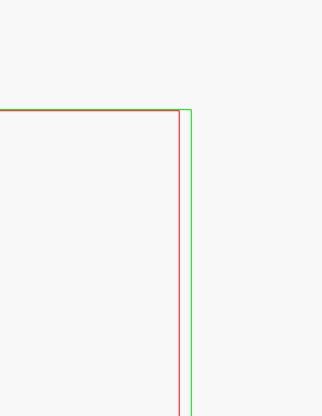
You’re right, It was designed for 3mm thickness. And if it’s without kerf that’s brilliant. But then I have a problem somewhere in Lightburn obviously? If I open the same file I uploaded here (lb_test.lbrn2) and zoom all the way in, the finger is now shorter then the slot - before it was longer (as posted above in screenshots!). The only thing I did was I closed Lightburn and now reopen it. I don’t get it! Before the finger was too long, now it’s too short. In neither case not the same lenght as when you open it… I really don’t understand what’s going on. And another thing - these same files were cut once before - a few weeks ago, when I bought the design - and guess what. The parts were hard to get together, because of the fit being too tight! And those cut yesterday all the fits are too loose and I have to glue them together. Is that even possible? Same file, same layers, no kerf offset setting on the layers at all. This is driving me crazy now.
How could you include an unknown kerf in a design?
Not all lasers have the same beam (kerf)… mine changes depending on the lens I select.
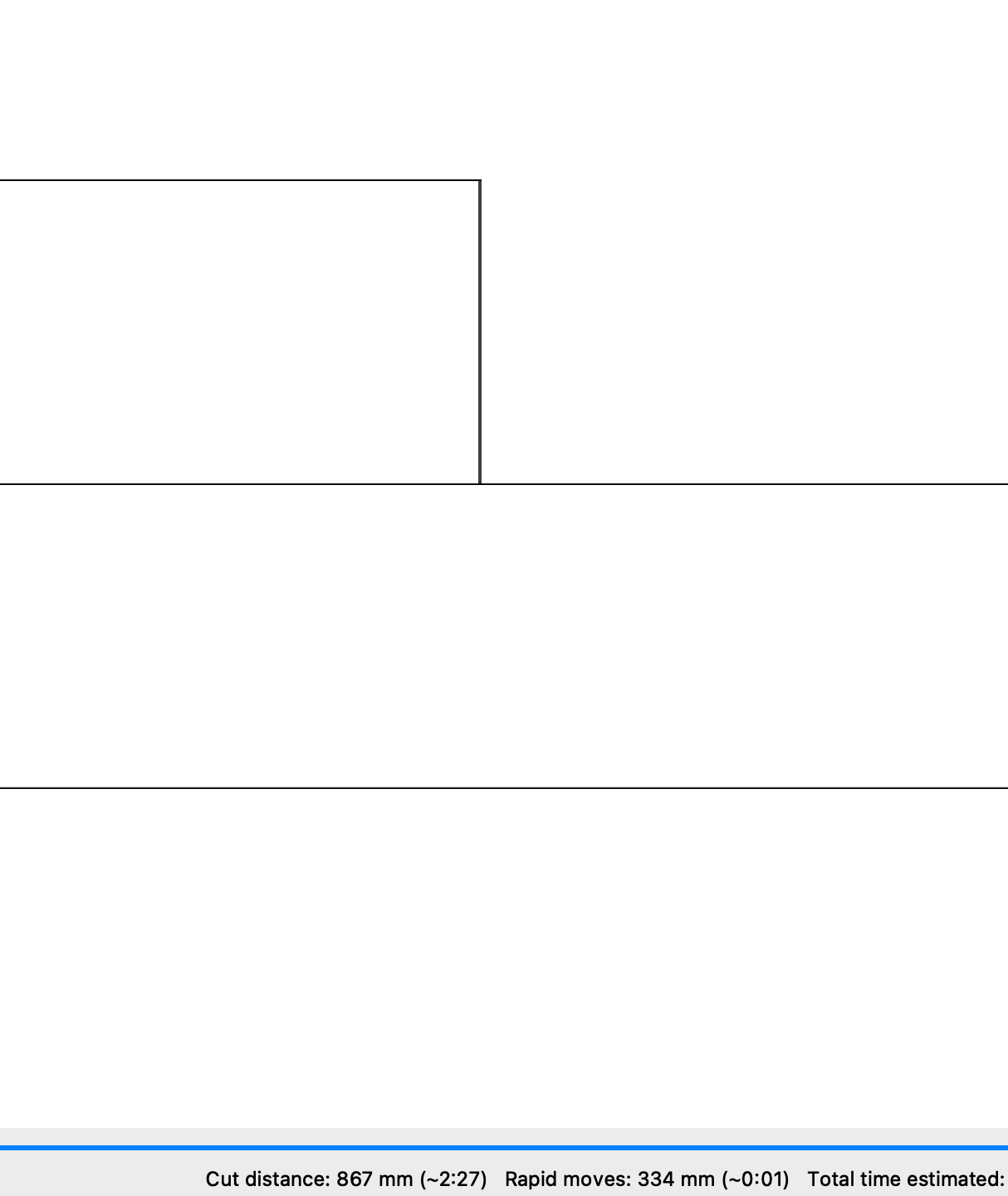
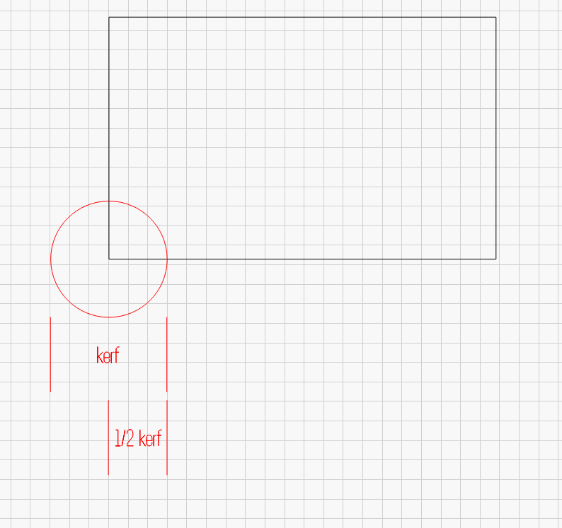
Simply put the ‘tool’ follows a path (black artwork). The tool is red, it will follow the ‘tool path’ of the artwork. You can see how the kerf affects the cut.
This depends on your definition of perfect. Some designs will have built-in adjustment for kerf. Others will make no accommodation for kerf. Some designs are descended from many generations of conversions. Part of it is knowing what you need and what the seller is providing. If the seller doesn’t know or can’t answer then that implies there’s little care in how it was made, simply doesn’t know, or maybe isn’t the seller’s original design.
This may also be a rounding error type of thing. Not sure what the original format of the files was that you imported.
That’s your call. To be fair, unless the seller was selling these as specifically LightBurn files then it’s hard to predict how exactly some programs will behave. They should work for the way that they were advertised, of course.
Some of the tabs/slots are fine. Others are not from what I saw. I didn’t check to see how much of an error there was in the ones I saw that were off. It may be insignificant compared to kerf.
That is a bit odd. But I would chalk it up to something on the laser or material side if none of the design has changed. Did you burn to the same material? Kerf for every material will be different.
Yes, okay, you guys are right. It’s most likely my fault, but I can’t figure it out. That’s why we discuss. I’m not saying the files are bad or not good. I’m just wondering (because I have to learn a lot more) why all the files aren’t prepared without a kerf compensation and each user would then enter its and do the cut. Maybe it’s easy to solve this now, but I don’t know how and that’s what arguing me. Is there any easy way to know what kerf offset were the files I’m buying built/designed and then somehow just correct it with my settings, without changing the design itself? I looked again and the seller doesn’t state anything about the kerf - so it’s on me to figure it out? I could sure ask him, but is there a way to somehow measure that? And is it possible to set the kerf offset in negative also to correct my problem?
Now I’m running a cut of these damn houses, will se what I’ll get out today. I checked the layer settings before cut - kerf offset = 0. The only difference in all the stuff now is that I’m using one computer for designing (from which all the screenshots are) and another one in my shop, connected to my laser. So it’s possible that there are some differences between Lightburn configurations. But could anything else except the layer kerf offset impact/address my problem?