You could ask or test fit the parts. In this case it’s a mixed bag. Or you find a seller who is reliably good and always stick to those. But at the end of the day nothing is going to eliminate the need to know what you’re dealing with if you want predictability and control. However, this might be a moot point. Most of these files will work if just trial and error your way through. Then just make note of those settings for that particular file and material. This won’t allow you to generalize the knowledge but that only matters if you care about a predictable and generalized workflow.
Ultimately, yes. You could assume there’s no kerf designed in but that doesn’t always hold.
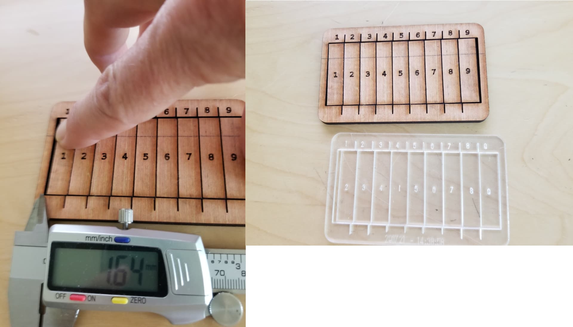
Yes. By fitting parts or using the measuring tool.
Is there a reason you’re stuck wanting to do this with a negative value? I thought I was clear on this but maybe not. A positive value should make your parts fit tighter which is what I thought you wanted. The bigger the value the bigger the adjustment. And again, the kerf offset should be half of the measured kerf since that’s how much the cut path will be outset.
Oh man! I was sure that raising the kerf in positive would make my parts even looser so I didn’t want to play around. Damn I’m dumb. If I just would have tried I didn’t want to mess around and have cut all that out so I can deliver my order. I’ll give it a try… I already did measure my kerf - by Rich’s video while ago - cut 12 parts, put them together and measured the width left - divided that in 2 and I got around 0.096. Then I tried with 0.100 kerf offset and it worked well.
Born stupid
Another thing to consider… The default Lightburn DPI settings are at 96 for Inkscape… if your files were designed in Illustrator, it’s 72. You’ll need to change this under Settings - File Settings… I got nailed on this with some etsy designs last month.
Hi, just wanted to comment that dividing by 2 your kerf is not correct; Rich pointed out the mistake he made from what I recall. Also Lightburn when using kerf compensation uses the full width of the laser’s kerf and the adjustment is done by Lightburn by halving the kerf width for the corrected path.
As a guideline add a worst case scenario for the thickness of your material. I use +10% for birch plywood from the nominal thickness, for example 3mm ply nominal is adjusted to 3.3mm. This is my prefered method when doing batches of cuts etc with multiple sheets, this avoids having to measure the thickness everytime for your material and wasting time on adjusting your drawings unless its a one off or very low volume production.
I’m a bit confused, either I haven’t understood how kerf compensation works or I don’t understand what I’m reading.
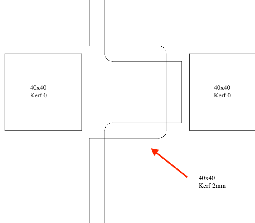
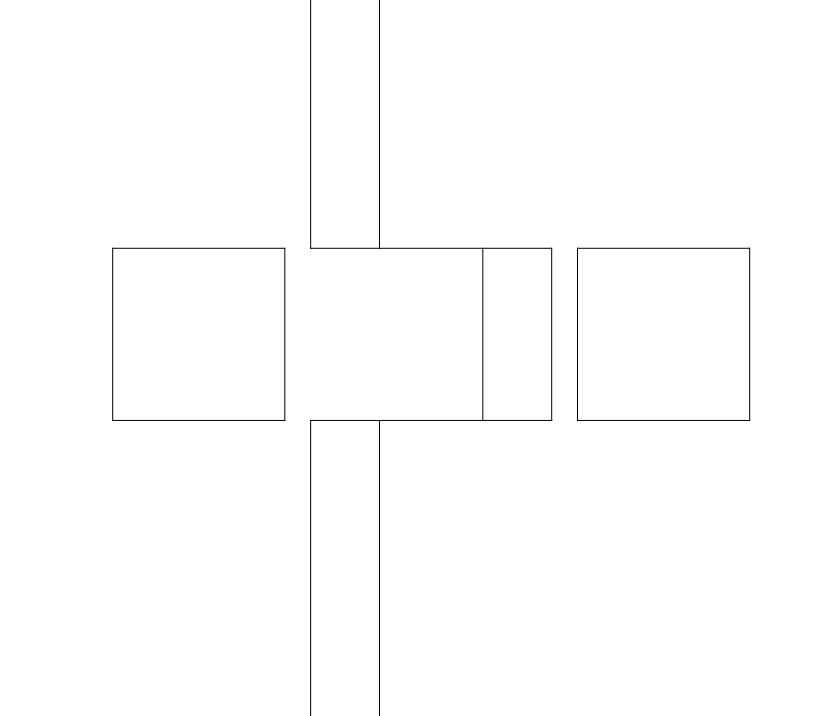
In this example there is a connection of two elements with (very large ) kerf. Picture is from the preview window and if I cut it out of cardboard - this is also what I get.
Hi, the way I worded it is probably not clear - the kerf when entered into Lightburn is the full width of the laser, when the path is corrected in Lightburn taking into account the kerf, the offset is half the width of the kerf; i.e the centre of the laser dot. So halving your measured kerf after a kerf test and using that resultant value as your kerf in Lightburn is going to make it tighter than it needs to be - probably too tight in some cases. Yeah in the cut set settings editor dialogue box it says “kerf offset” but that is not as I understand the actual offset it is actually the full kerf of the laser itself.
I believe this is incorrect. The kerf adjustment as input is precisely how much the offset is applied. Since you only need to account for half the width of the kerf you need to input a value of kerf divided by 2. If you enter the full value of the kerf you will be overcompensating.
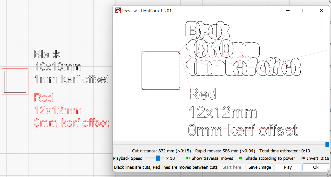
Check out this setup. Black has 1mm kerf offset configured. Red has no kerf. Note how in preview that the two objects overlap.
Hi yeah seems I misinterpreted the dialogue box - to be honest I think there should be an option to put in the laser’s full kerf width and let Lightburn do the offset calculation instead having to make the user do the extra legwork of dividing by 2. Somehow I got stuck into my head for some reason that the kerf offset was the actual kerf width.
Kerf adjustment is odd, if you think about it. Most of the plans I’ve worked off of show the object as drawn with no ‘clearance’ in the measurement.
So if you put the kerf at 1/2 of it’s offset the parts would be exactly on the tool path, pretty much ensure they will not fit. Everything that ‘fits’ together needs some kind of clearance and you can use the kerf adjustment to do that. Exactly what we are using it for.
If 1/2 the kerf is 0.1mm and you want to make more clearance between parts, say an increase of 0.01mm, you may need to go with 0.09mm… Do you want to have to multiply this by 2 to get the 0.18 setting to enter it just so the software can divide it by two…?
If you cut a board with a table saw, you use 1/2 the saw kerf to ensure the parts come out measured correctly. Instead of cutting down the line, you adjust the edge of the blade to the line. This is 1/2 the saws kerf.
Keep in mind that if you set a kerf for all parts, there could be fitting issues. Especially when you have a box top and sides…
Get used to using it, it’s a great and powerful option.
Just a thought that has nothing to do with it maybe…
When I write a G-code program for the shop CNC and I want to set the kerf so an object will fit well I put a positive number in the the offset. I guess experience tells me what I need but with the CNC and router bits you have the need to account for a bit that may have been reground. That is when I use a positive number which makes the bit move further from center outward making the cutout larger. Smaller circle for instance would need the offset to be negative.
Laser cuts a narrower path but same situation.
Suppose I have multiple pieces to a file. Some are slots/cutout circles, rectangles, or squares. for instance. If I select all of those in Lightburn I can resize items the same size to other dimensions or apply a percentage to the original increment and change all that I have selected. This makes resizing slots in LB to fit different thicknesses of material easy.
Well, anyway I know what I mean. lol
If the correct adjustment for the tool path is X amount of kerf to cut the actual design or tool path, then a tool <X has to have a smaller kerf for the same results.
Maybe LB figures the positive/negative opposite to what I learned for the CNC.
Jack I see where you are coming from. I am considering my adjustments according to the tool size.
Now, My original 0.5" bit is ground and is now 0.490"
To cut a circle of the same diameter I will need to adjust the offset of the bit 0.10 positive to make the same size circle.