I am a PhD student and I have been starting my research for a few weeks now. After several days I have realized that the information shown in the preview does not correspond to what the laser engraves on the plate. The corresponding blacks between 60% and 100% are practically the same, the image definition is lost. And the whites from 0% to 30% disappear, the laser is not able to engrave it. It is as if when you press play the laser interprets the image.
Does anyone know why this happens? I would need it to engrave exactly what the preview commands.
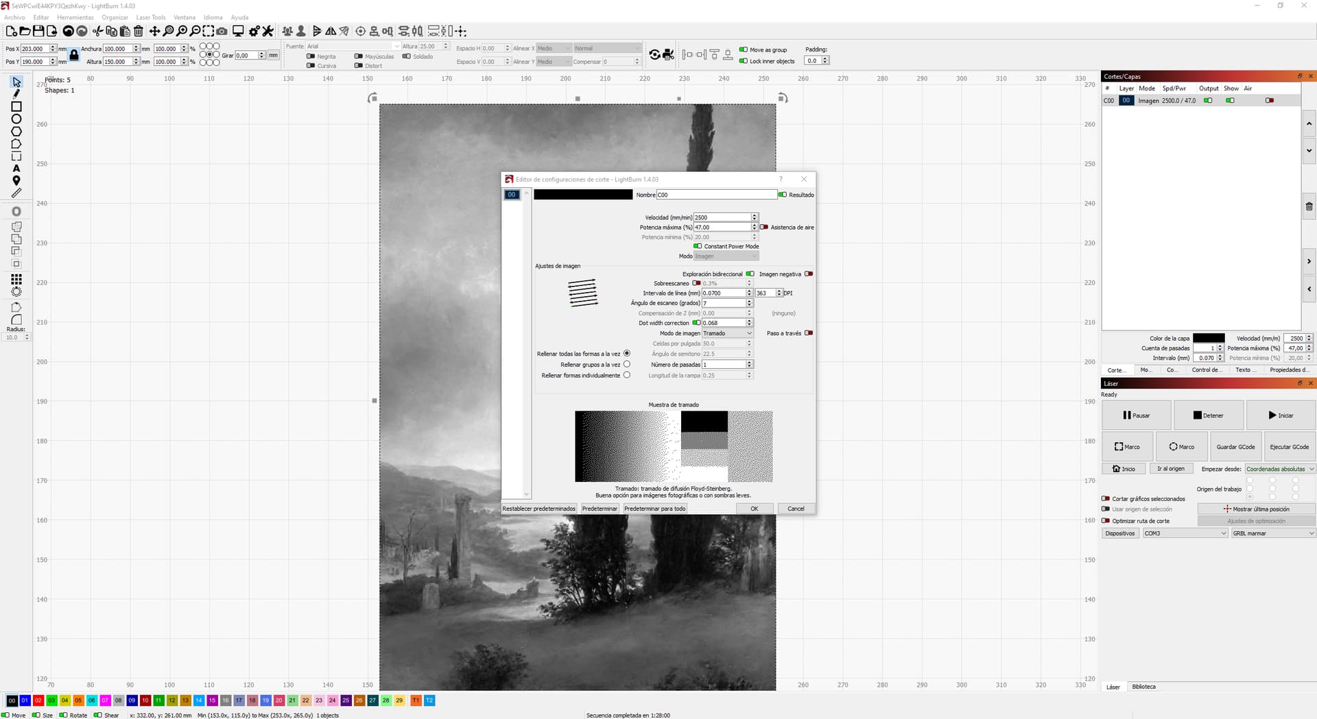
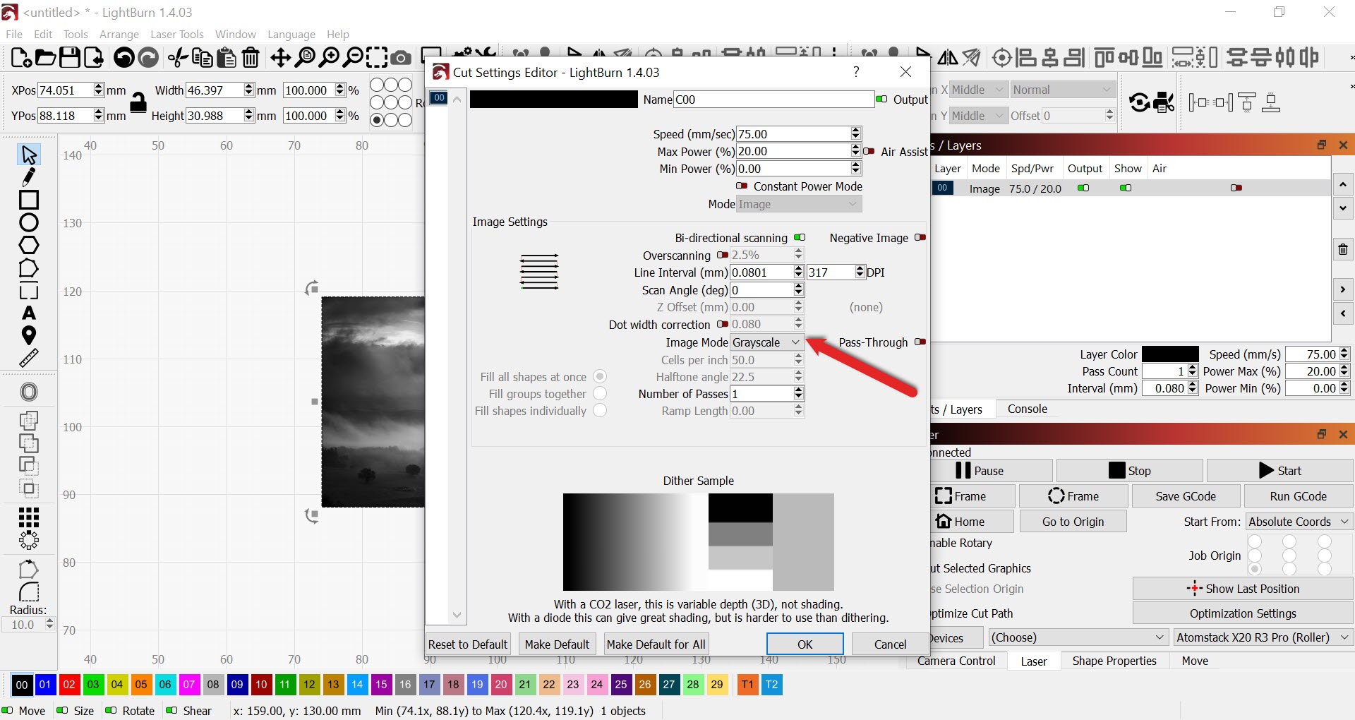
I rarely play around with images so am totally unsure, but just wondering if the fact that ‘Constant power mode’ is selected would have a bearing on what you are experiencing.
I have tested by varying all kinds of parameters. In the last tests I selected the constant power mode because it avoided an annoying “moiré” that I had in the previous tests. Now I get the engraving to look good but it does not record exactly the dots that are in the preview, but an interpretation. I lose a lot of tones in the final engraving.
I don’t know if there is some parameter in the CNC configuration that is not correctly set.
Laser engraving photos with full range of contrast is practically alchemy. I’m not sure I’ve ever seen an example that didn’t clip on one end or the other.
Yes, this is very often the case. Diode lasers often produce a dark dot or no dot. This is most often true with ‘White Tile’ work. Dithering modifies an image for production with high-contrast materials.
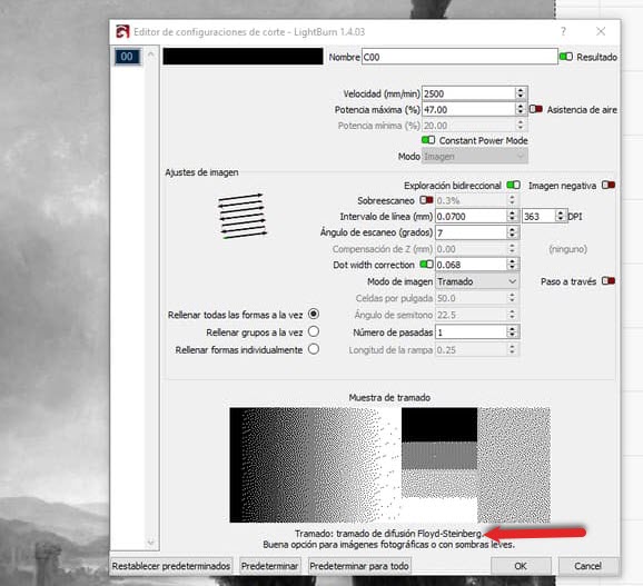
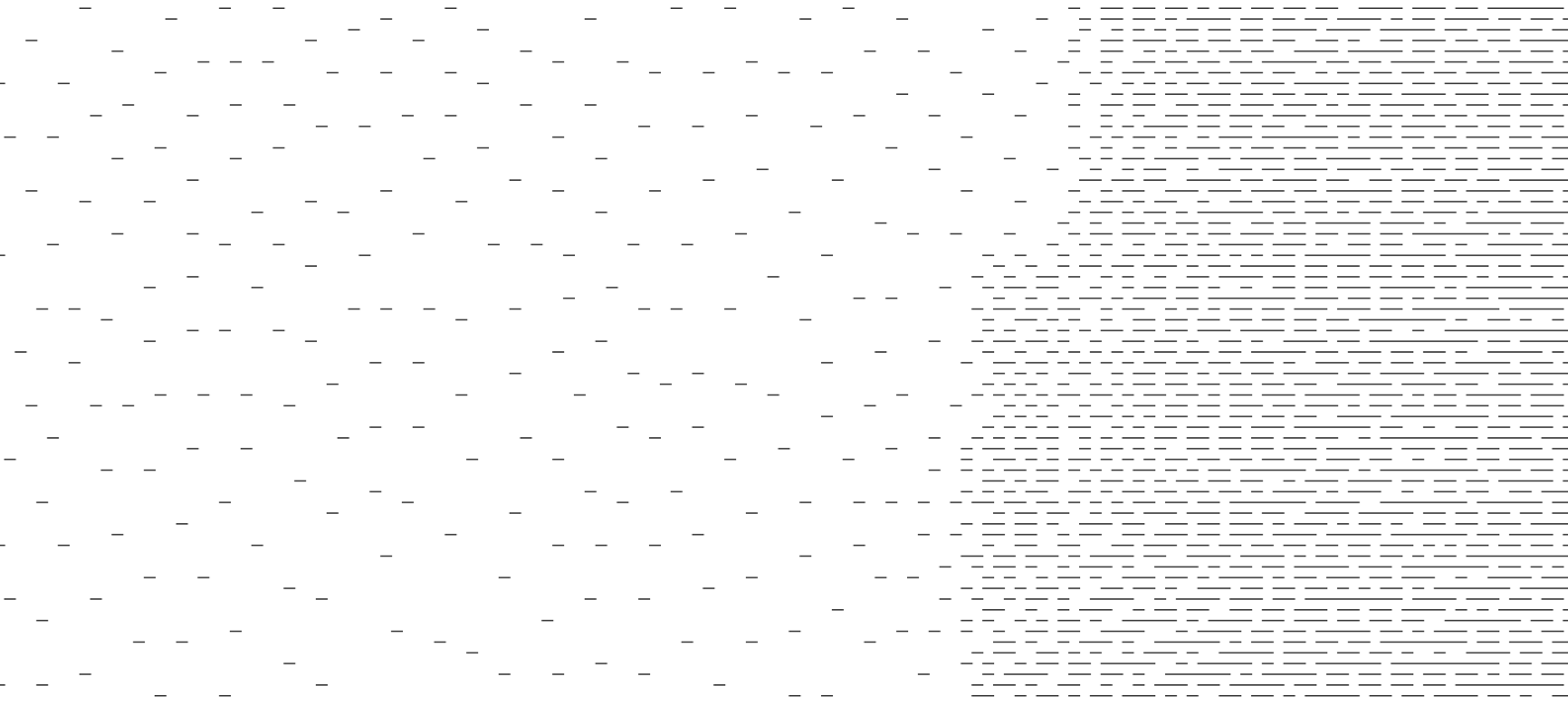
You have selected a Floyd-Steinberg for dithering which is a good approach and you are seeing this dithered image as it would be produced in the preview window.
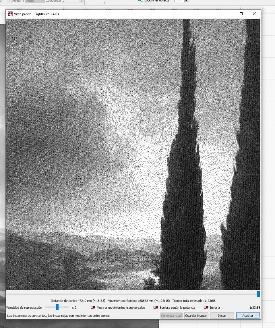
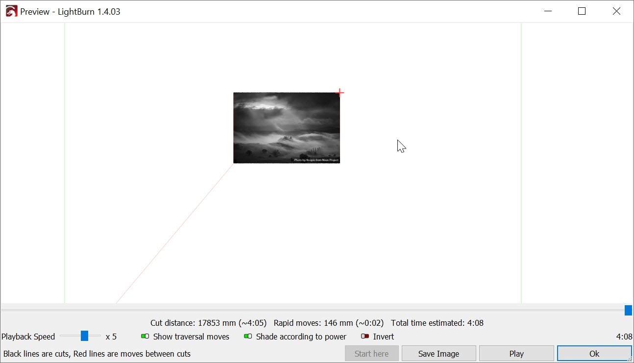
The Preview Window faithfully models the output that will be produced. It shows all dots, so it will produce Lighter than the expected output at a close view and dark with the view further back.
If you choose not to take advantage of Dithering select Grayscale.
I’ll start with this.
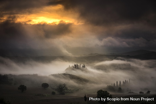
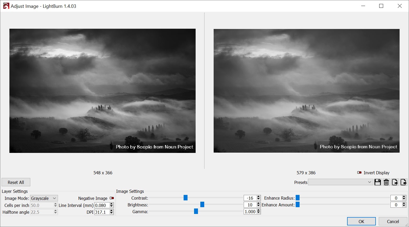
Hills covered with fog during sunset by Scopio from Noun Project (CC BY-NC-ND 2.0)
The material response is not programmed and there is no feedback provided by the laser engraver to calibrate the shading of the preview.
You may need to adjust your art in the Preview that is not intuitive to your eye to generate the range of tones in the darker shades.
Right-click the Image and select ‘Adjust Image’. To get more detail into the dark ranges reduce contrast and increase Brightness. It may look wrong in Preview but with some fiddling, you can get the image you want to be produced well.
Basically my problem is the laser doesn’t engrave exactly every dot in the preview. I don’t know exactly how the machine language works but ideally I would like to use binary language, where there is dot =1 and where there is no dot =0. I want to make some curves to compensate the dot gain but first I have to work out why the head doesn’t put all the dots as in the preview.
P.S.: thanks for the reply. I’m working now, when I get back home I’ll be able to post some pictures to make the subject more understandable, I think I didn’t explain myself well.
I can prove that what I record does not correspond to the preview, let me a few hours and I’ll put the pictures. I didn’t try to do what you said, it’s a good idea.
I think you misunderstand what the preview actually shows.
It shows you when it will lase. It cannot tell what you are lasing.
Even two identical machines will not produce the exact same results.
Might help if you can watch this video by Laser Everything on engraving photographs. Maybe that will help you understand what’s happening and greatly assist in your work.
This technique works with any laser and any material.
Good luck
Closest thing to a phd I’ve been with is my camera… the button on top says Push Here Dummy…
Hi, thanks for replying. I watched the video and it looks interesting, in short the subject it deals with is a subject I know how to solve. You asked me what my field is, I’m in the graphic arts. I work as a pre-printer. I am familiar with the subject of the video but it is not my problem. My problem is that the machine does not send information to film, parts that should be recorded remain blank, without dots. I am used to work with stochastic screen, and bitmaps.
Imagine you have a 3D printer, in the extrusion preview it shows you one thing but then the printer doesn’t put filament where it told you it was going to put it, well this is my problem but with the laser.
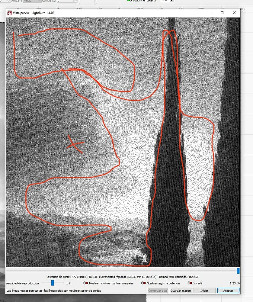
I am going to try to explain better. The areas that you see marked in red appear in the preview but when I start recording it doesn’t put any dot in those areas, it leaves them blank.
Is it possible that the preview is not real? I find it difficult to work in this way, without knowing exactly what data the laser is going to take as a reference.
The preview shows you when it will lase. It doesn’t tell you if there is enough energy in that lase period to effect the material.
It only shows you where the machine will turn on and off.
How much energy is transferred to the material is a speed/power relationship. The range from there being no damage to total damage of the material can be very small.
You will have a compressed area, exposure wise, in which to work depending on material.
What material are you using?
I’d suggest dropping the interval to 0.10mm or even 0.20mm, at least until you get a handle on what’s going on.
It’s much like exposing film when there isn’t enough light in the shadows to produce any exposure, even though you can see it.
If you are in Grayscale mode and if you are not pushing enough energy to mark the material then I feel it may be a possibility.
If you are willing to share the image file that you’re working with please feel free to do so, here. Someone may see what might be slowing you down.
When you posted earlier that you wanted a 0 or 1 output and exact transcription, then you may be looking for Pass-Through instead of Dithering or Grayscale. I think that may deliver your desired as-delivered on-off behavior.
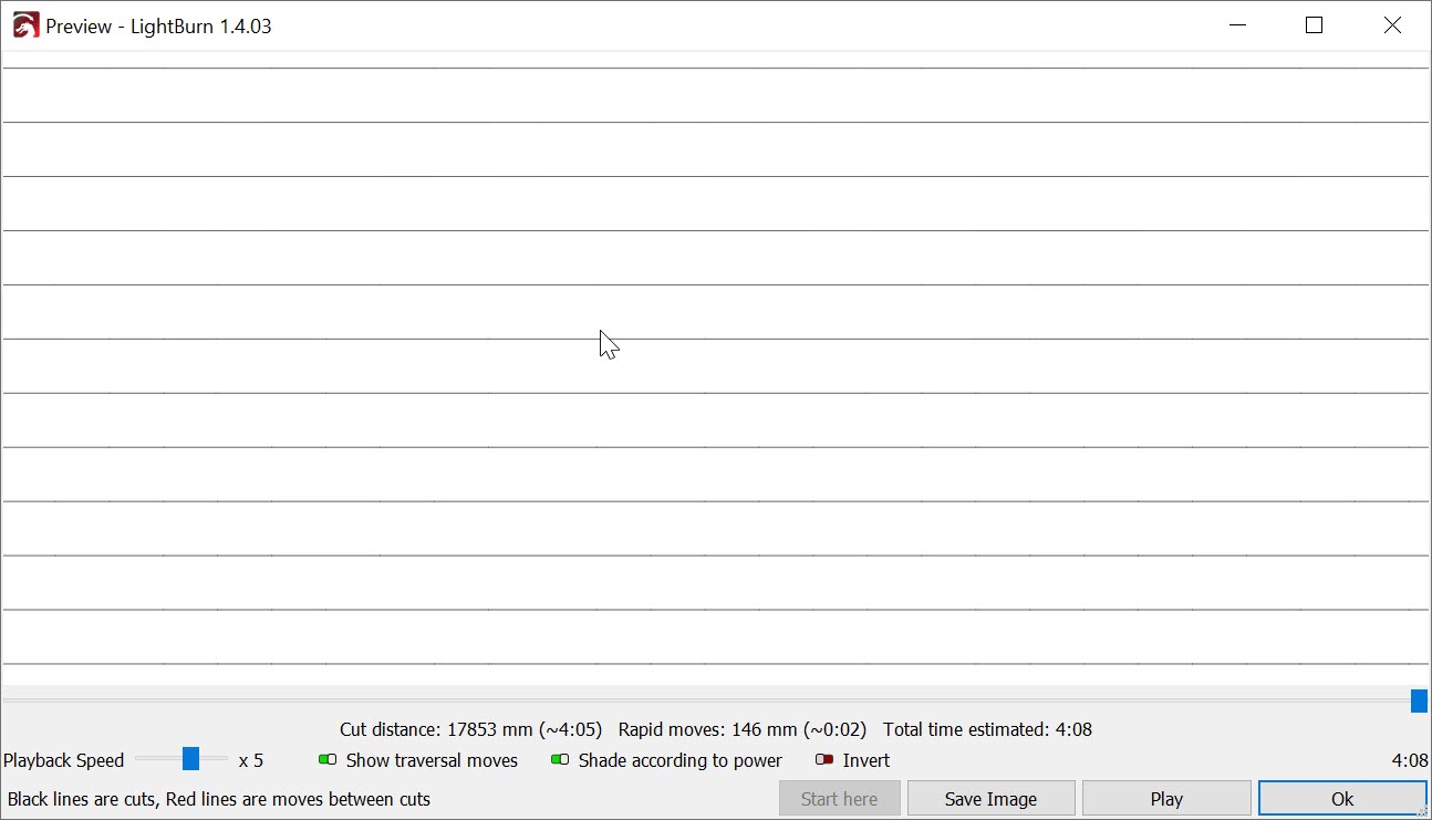
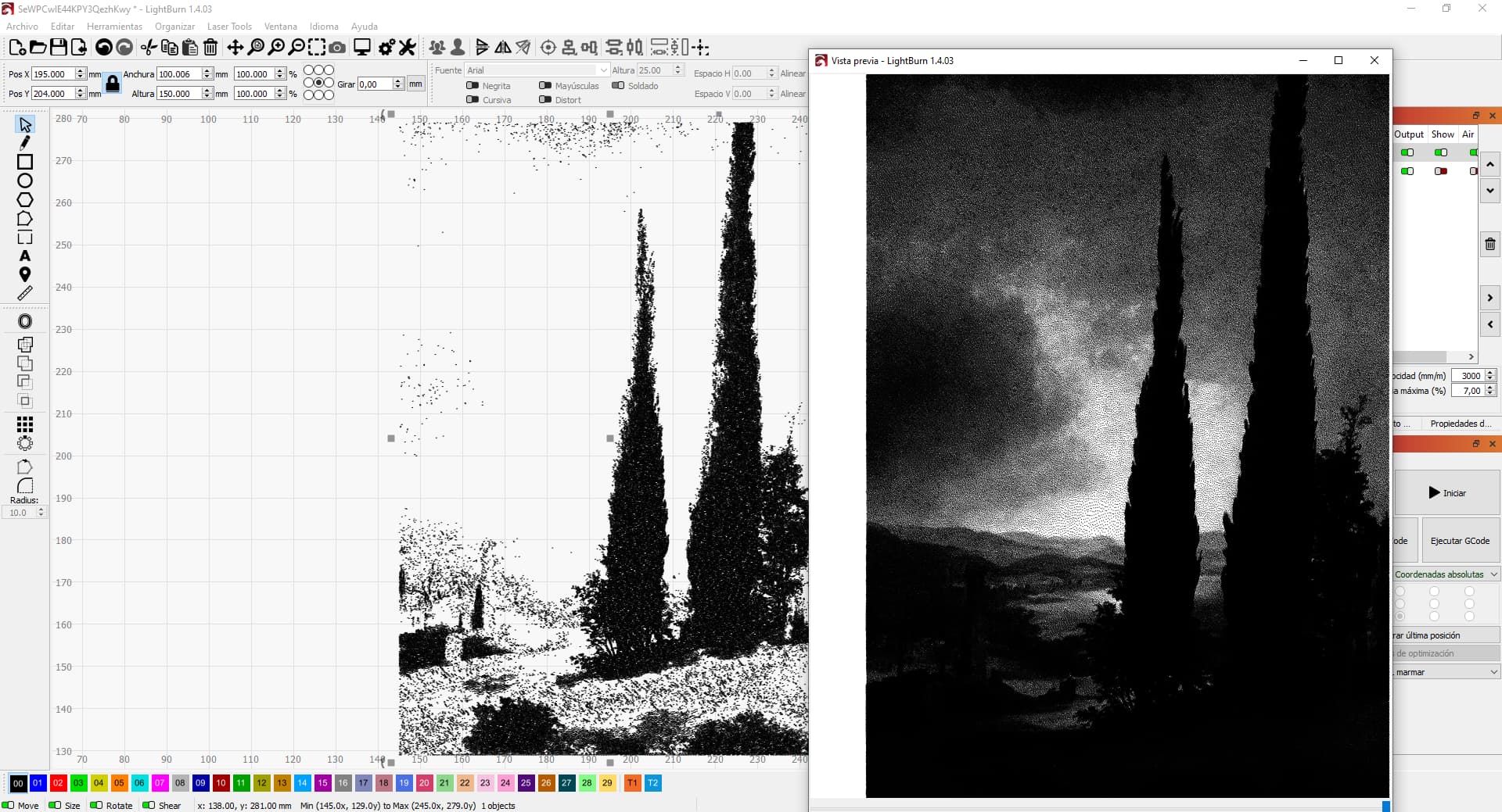
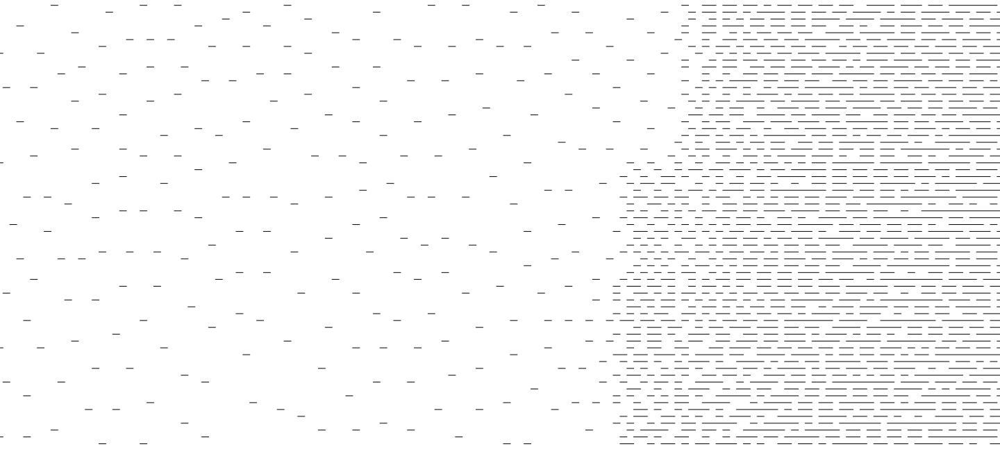
I attach the file. Also, I have saved the Gcode and reopened and the way it looks (left side) is what exactly it records on the board. The right side is what the preview shows.
Interestingly, what the Gcode shows looks like what it records on the board but if you look at the preview you see again something similar to the grayscale image preview.
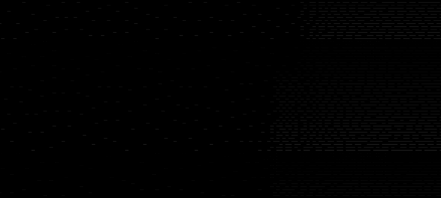
I spent some time analyzing the file. In general, it seems to be working as expected. All paths with one exception that I’ll note below are represented in the g-code.
The difference is essentially black. The only differences identified were from small aliasing differences in the generated raster Preview. The paths themselves seem identical.
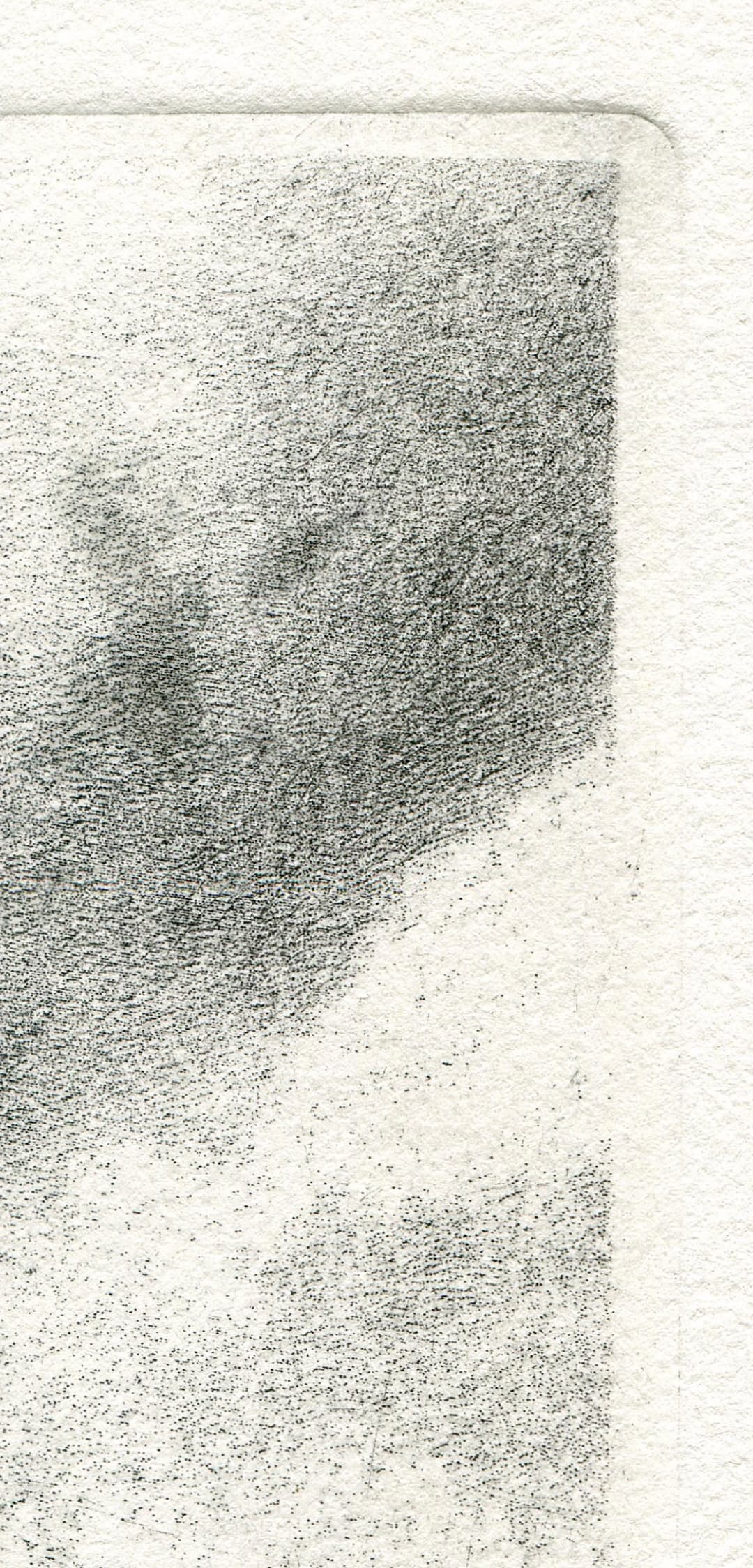
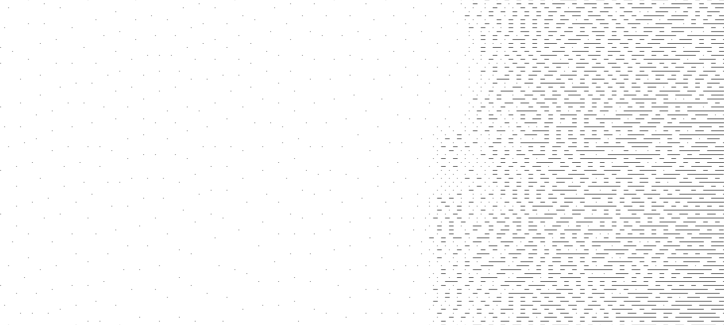
However, as noted above I did find some artifacts that did not come through in the g-code. From tests it looks like this is due to enabling of “Dot width correction”. Note that with dot width correction enabled there are some extremely tiny marks in the Preview for the image. However, these do not show in the g-code.
If you look carefully, you can see some very small dots in the image above. I suspect those are the fragments left over after dot width correction is applied. I further suspect that those are too small to be sent to g-code and so is omitted. However, that’s pure speculation.
Note that I changed the scan angle to 0 degrees for these test to make things easier. I saw the same behavior with the original scan angle, however.