Hello everyone. I’m new to using a rotary with a fiber laser and I’m having a little issue that has been stumping me. Whenever I’m engraving diagonal lines they are not straight as they should be, they turn out wavy.
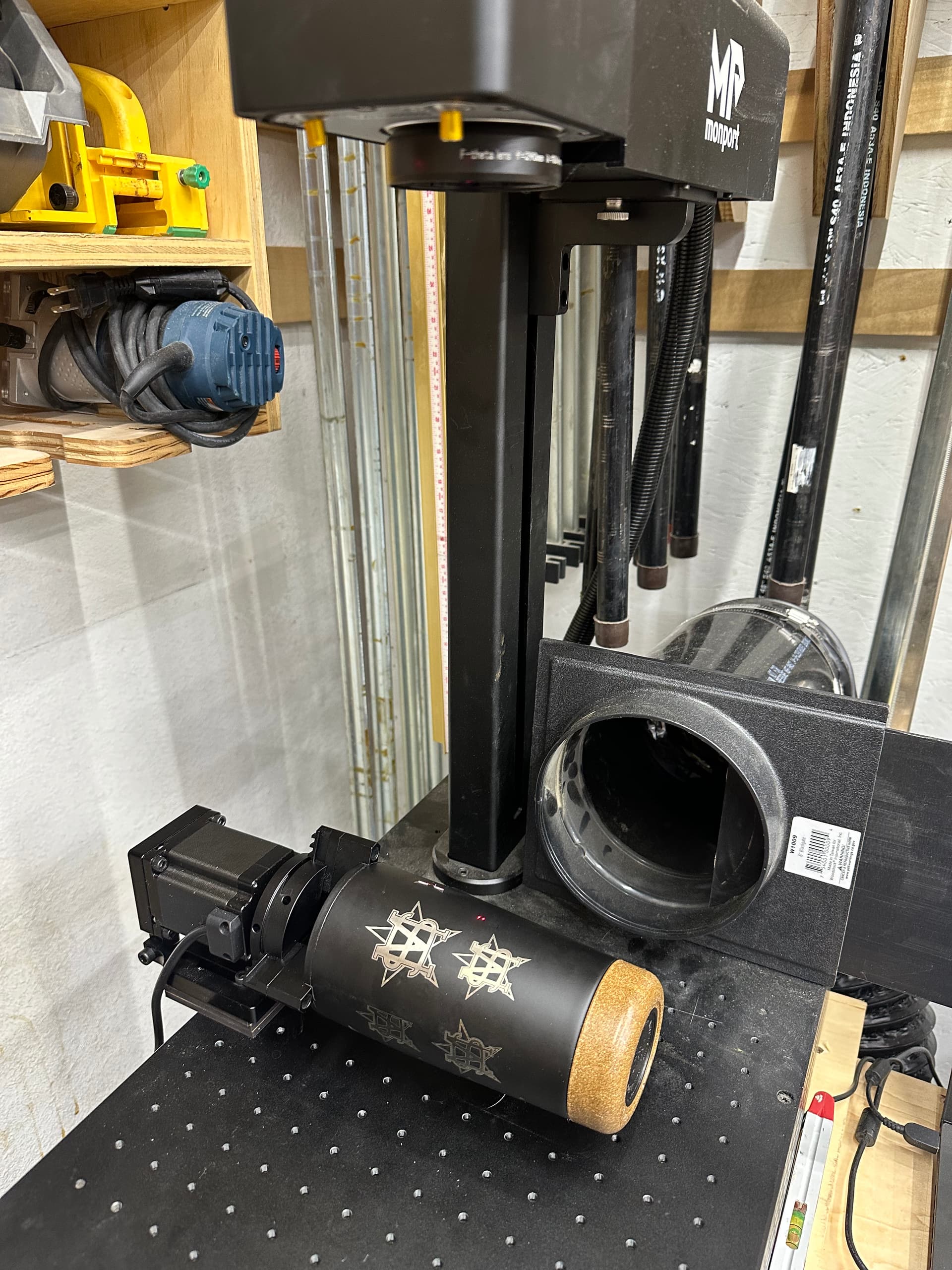
Using a Monport GI60 fiber laser with a 200mm lens. Cor file has been installed and I have gone through the 9 point lens correction in LB. Haven’t altered anything with the timing however. Rotary is square and cup is level to the laser head, defocusing 5mm. Flat engravings come out fine, this is not an issue.
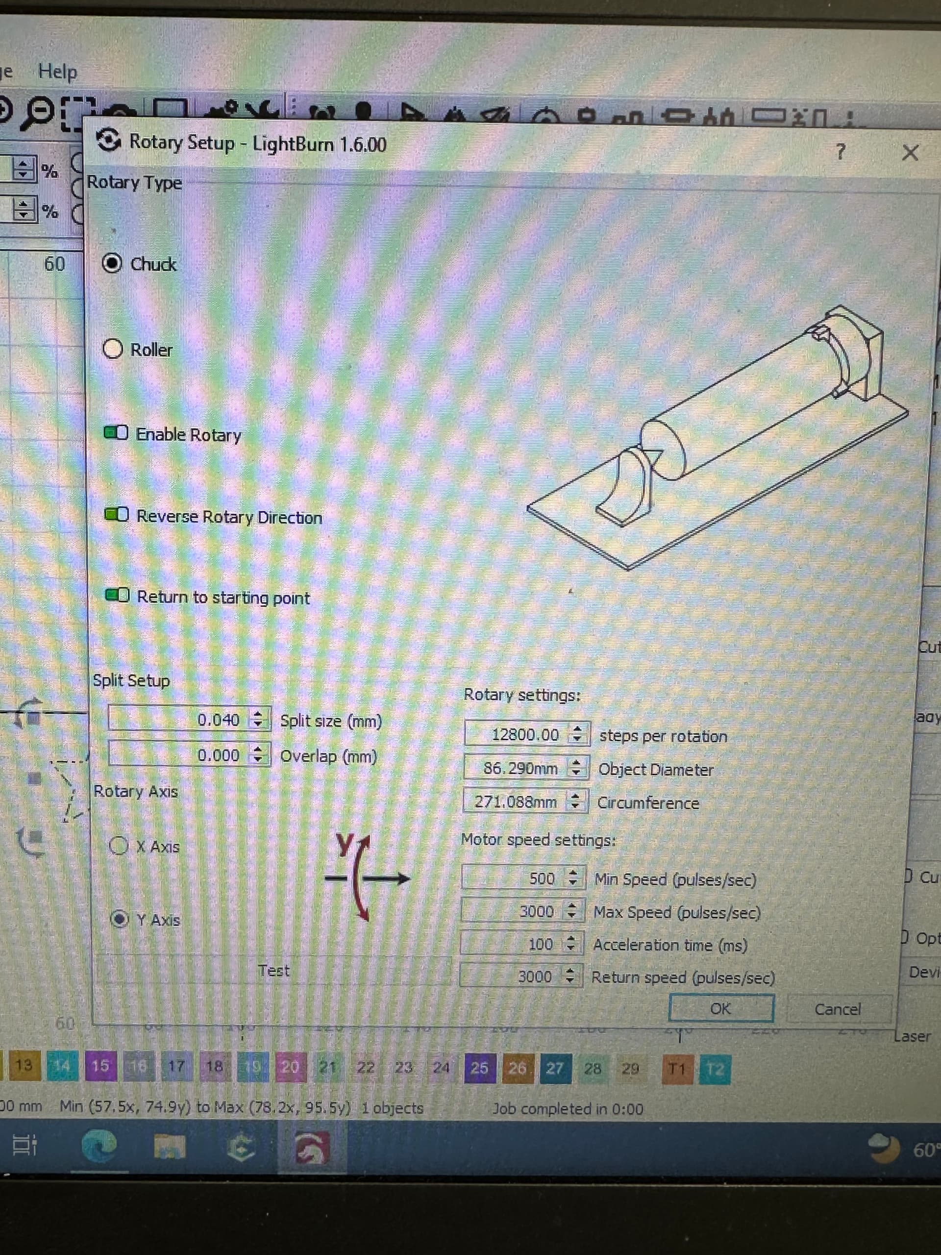
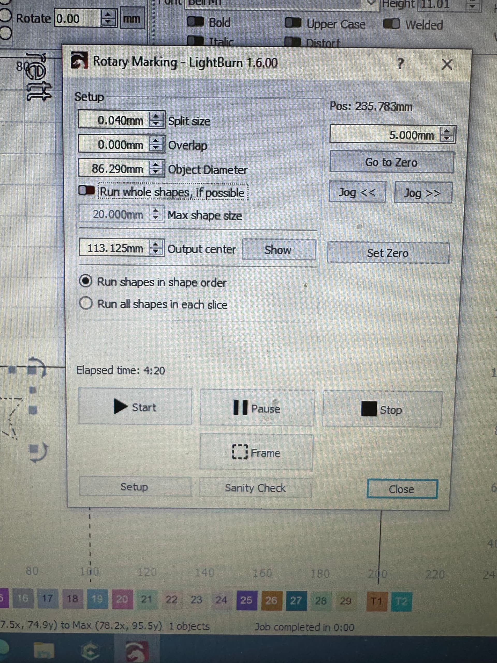
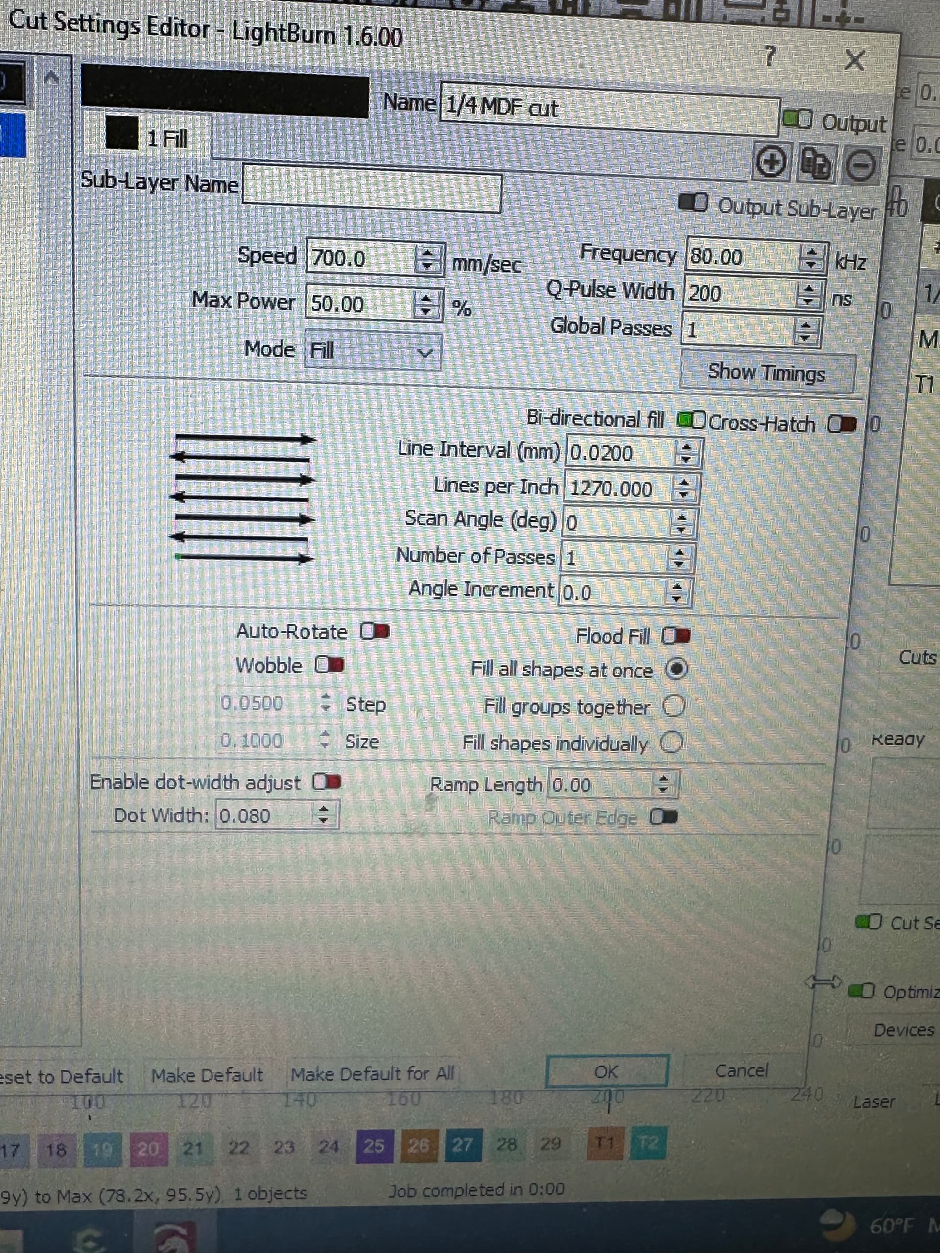
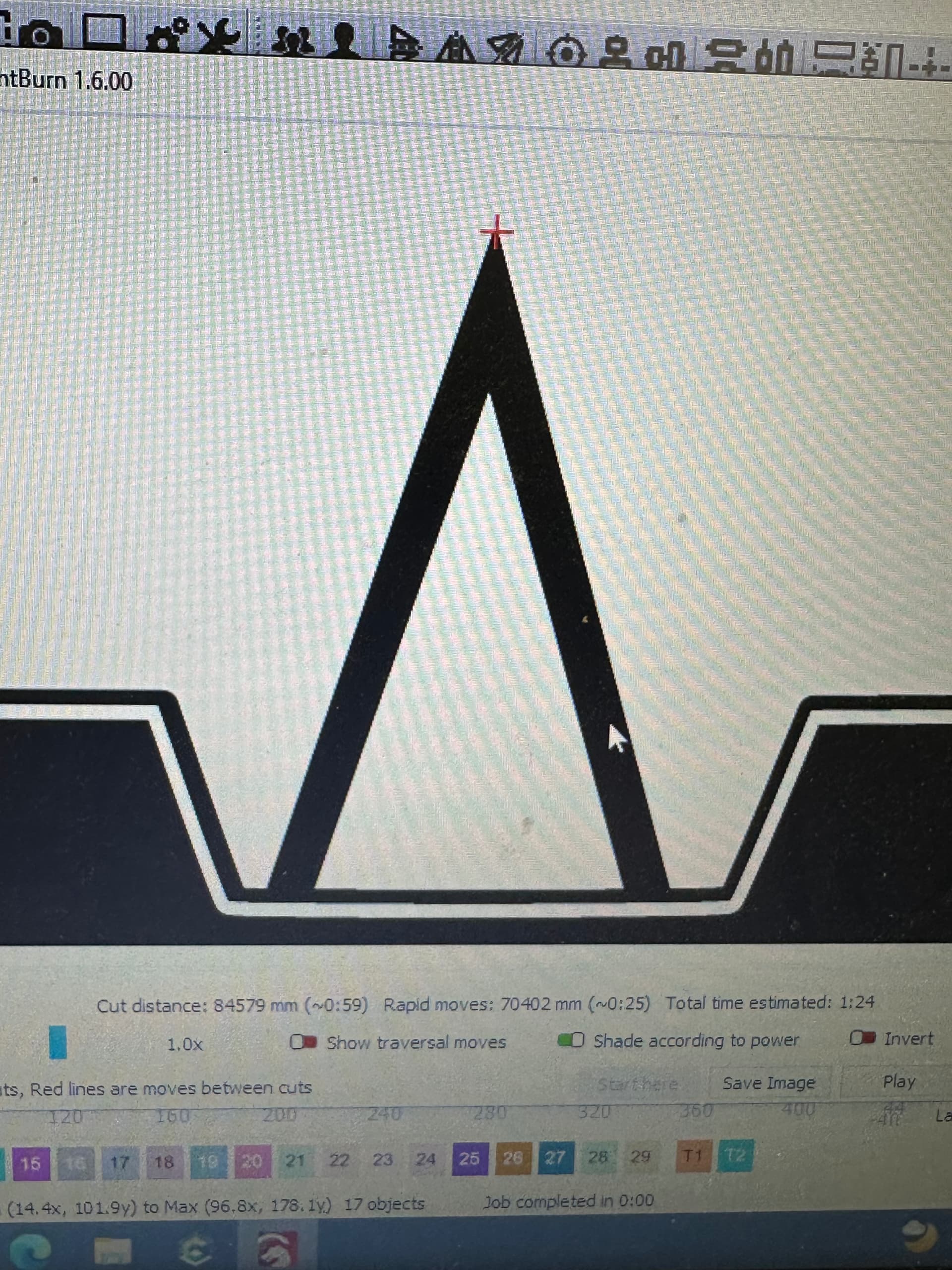
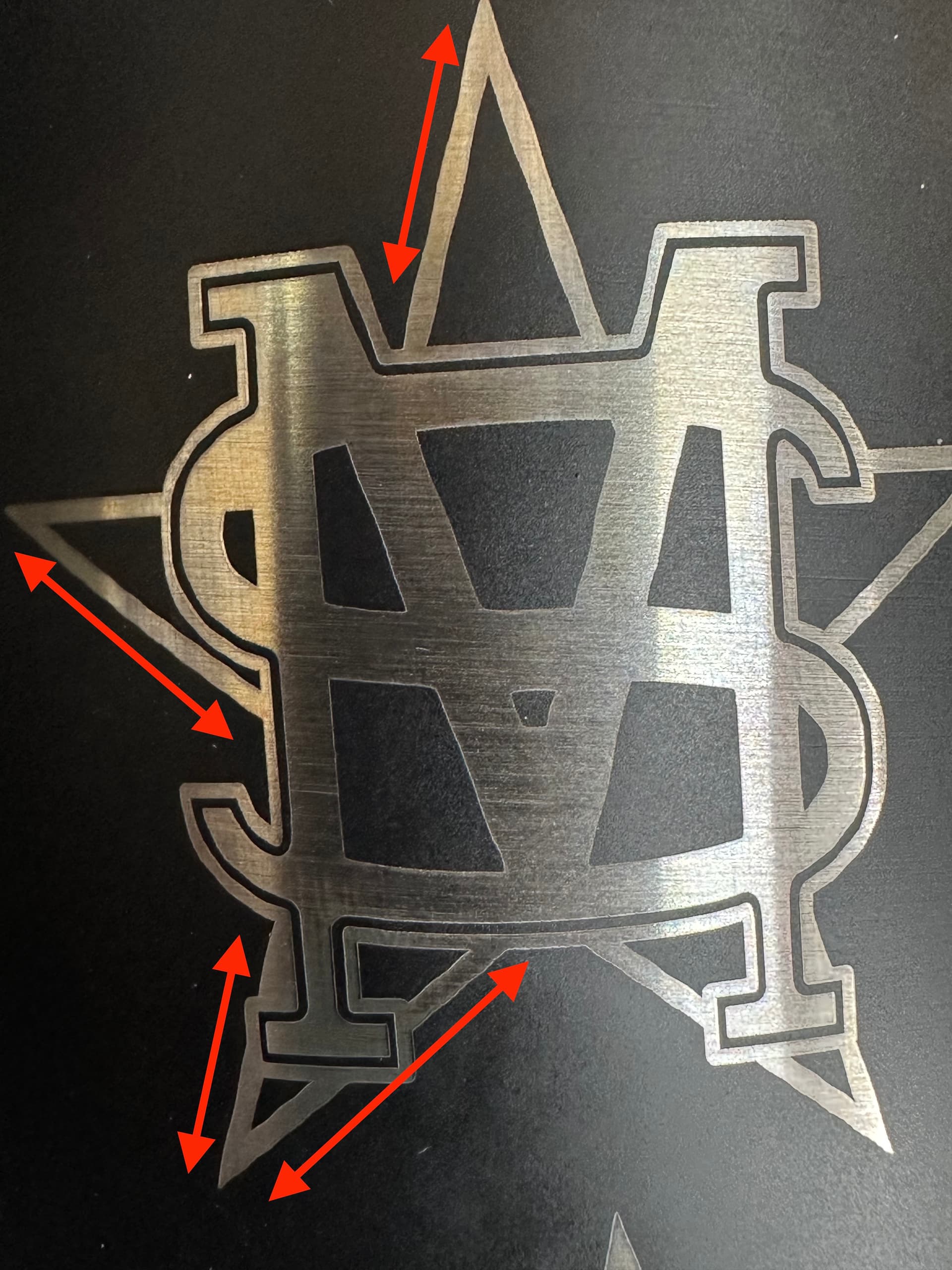
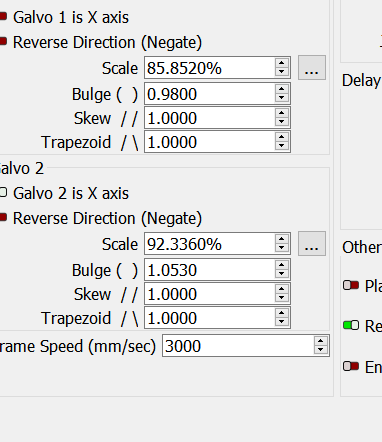
At first I thought this may have been something with my file but my preview shows nice, crisp edges all around. I’ve attached my rotary settings and my engraving settings as well as an example of the issue with some of the trouble areas marked out.
Does anyone have any thoughts on this please? I’ve searched the forum but mainly found threads related to c02 gantry machines. Thanks a lot.
Hello
First off your split is really small, should be 10 to 100 times what you have now. Your rotary can’t even stop at 0.040mm, when it tries it will probably stop at 0.042, see below.
Second, dividing your circumference by your total steps your surface moves 0.021mm (actually 0.02117875mm) with each of the 12800 microsteps, so for smoothest operation you should make your split a multiple of that, say X25= 0.53mm (0.52946875) See if that smooths out the edges. This can also be applied to your line interval, instead of 0.020mm try 0.021mm. Scan parallel to axis.
Your other settings look right on.
Thank you Al, usually i thought split size was supposed to be your line interval or multiples of it. Again, I’m new to rotary setup so just sharing my thought process.
I will give that a shot. Do you recommend running any overlap with a larger split size like .53mm?
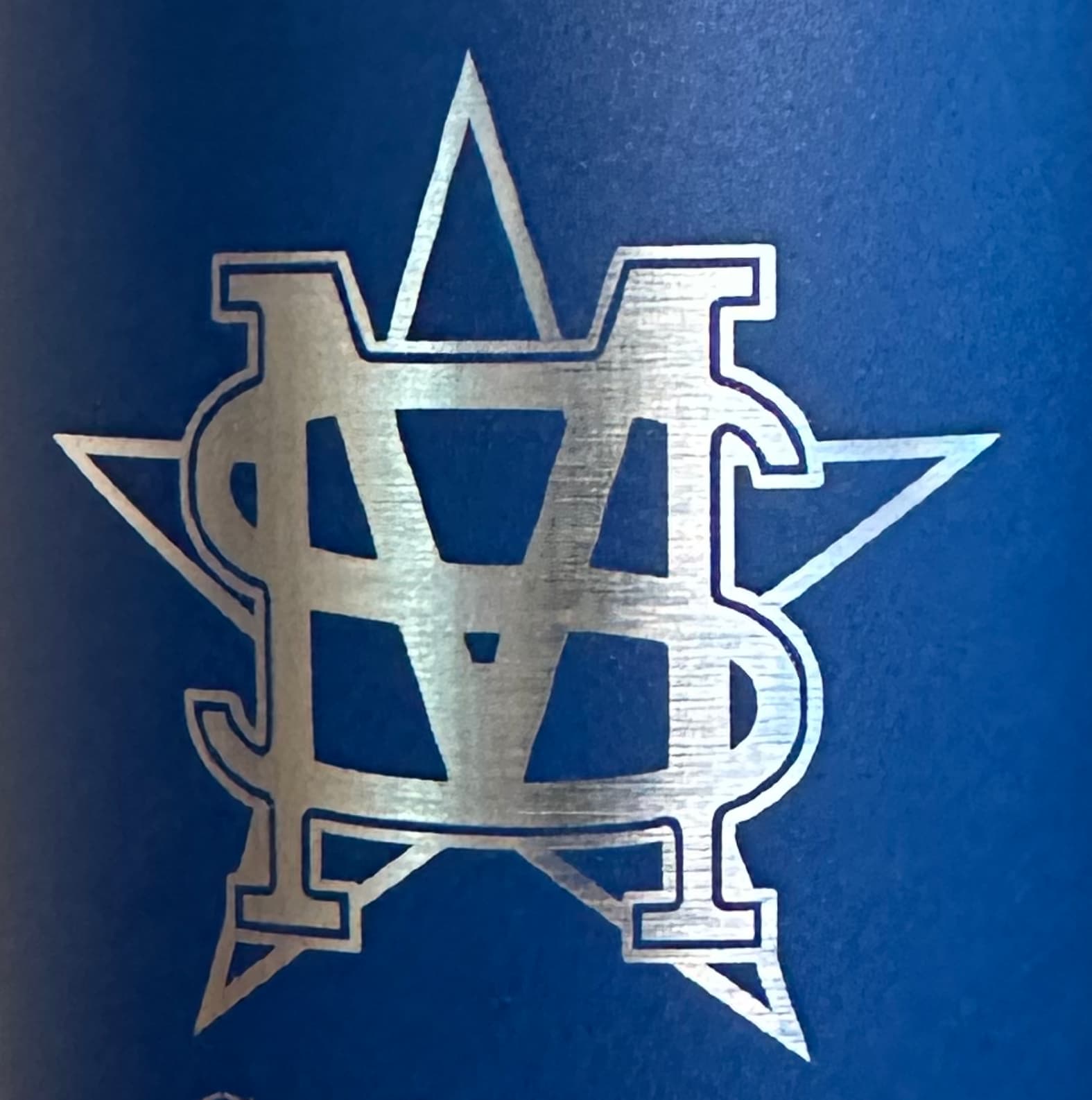
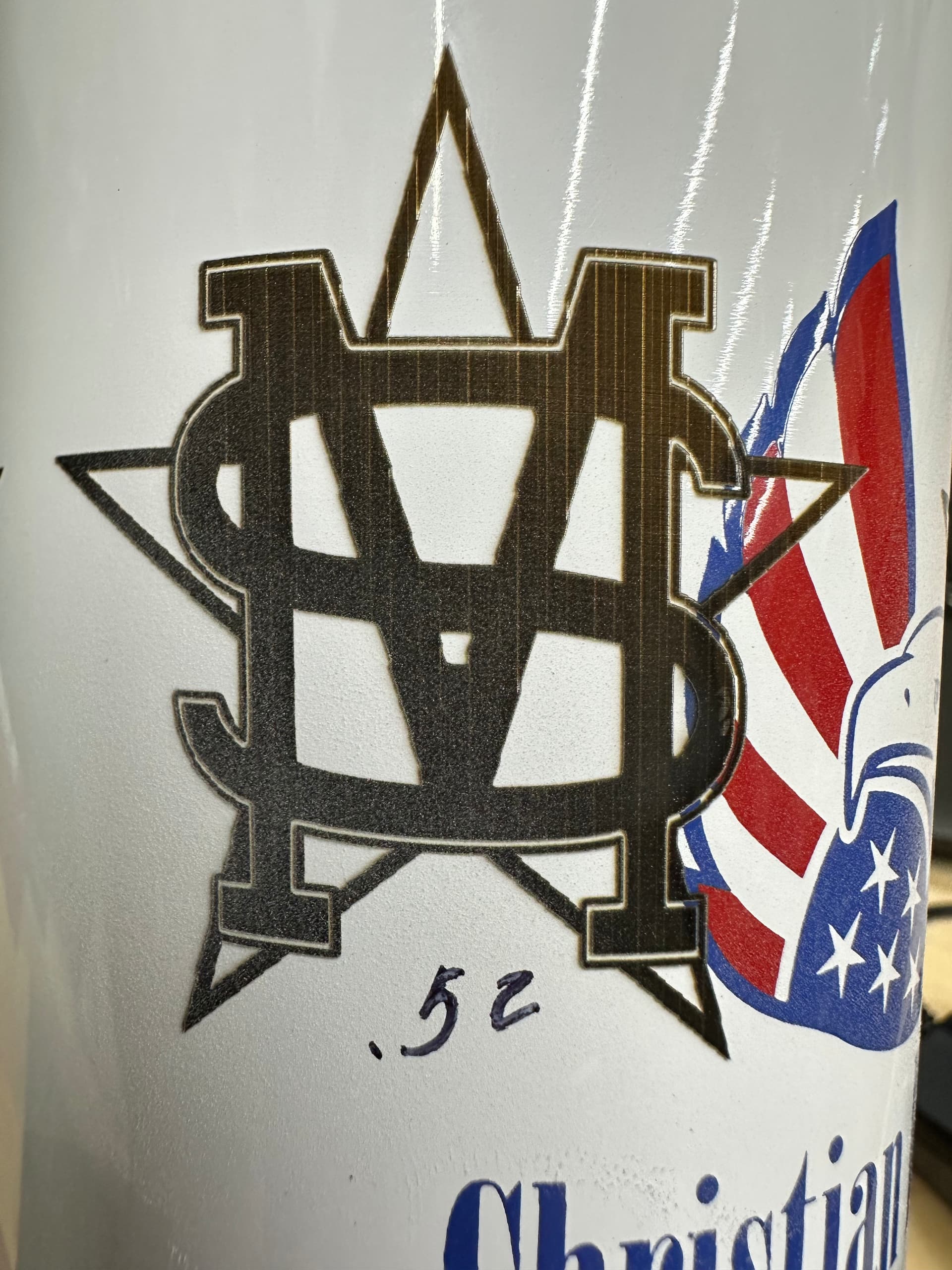
Here’s another picture showing a finished cup with my settings from my original post. I didn’t even notice the waviness until my wife pointed it at at the top of the star. Am I being too picky now? I can’t unsee it now and it’s bugging me lol.
A good split size makes a big difference. @Albroswift is correct with his description of how the rotary steps…
The other part of this is depth of focus (dof) of your lens. We think of it rotating and lasing, but when it needs to rotate, Lightburn sends the rotate command to the rotary and waits for it to acknowledge that it moved. The speed of the rotary is nothing compared to the galvo… if you want the fastest job on a rotary, make the best use of the galvo/lens/split size combination.
If the dof you your lens is 5mm, then you can focus below the top of the object by 2.5mm or 1/2 the dof for your lens. The beam will stay in focus for that complete vertical distance allowing you to greatly improve job time using a much larger split size and letting the galvos do most of the rotational axes work.
I started a new cup just now and tried to follow what you recommended. Here’s what I did.
My new cup had a circumference of 268.166mm. I took that number and divided it by my steps per rotation (12800) and got .02095mm. I then took that number and multiplied it by 25 and got .5237mm. I rounded up and used .52mm as my split size. I reran my test using the same settings and .021mm as my line interval and these are the results I got. Lines are straighter but I would say they are no “choppy” instead of wavy.
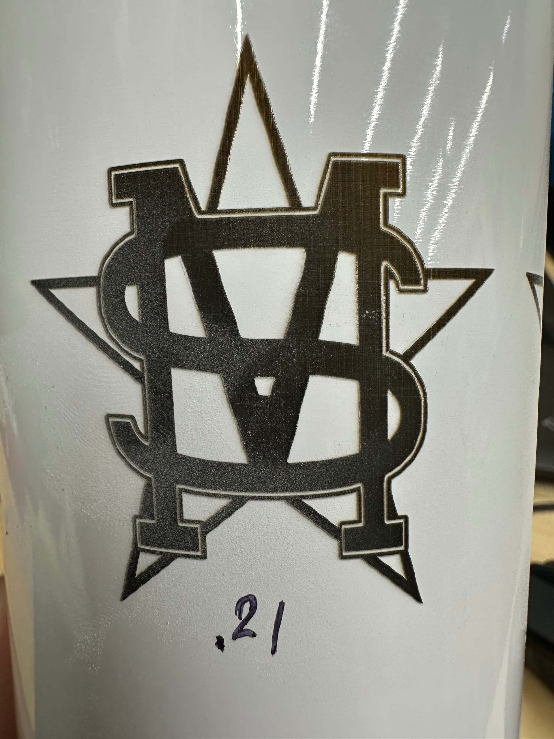
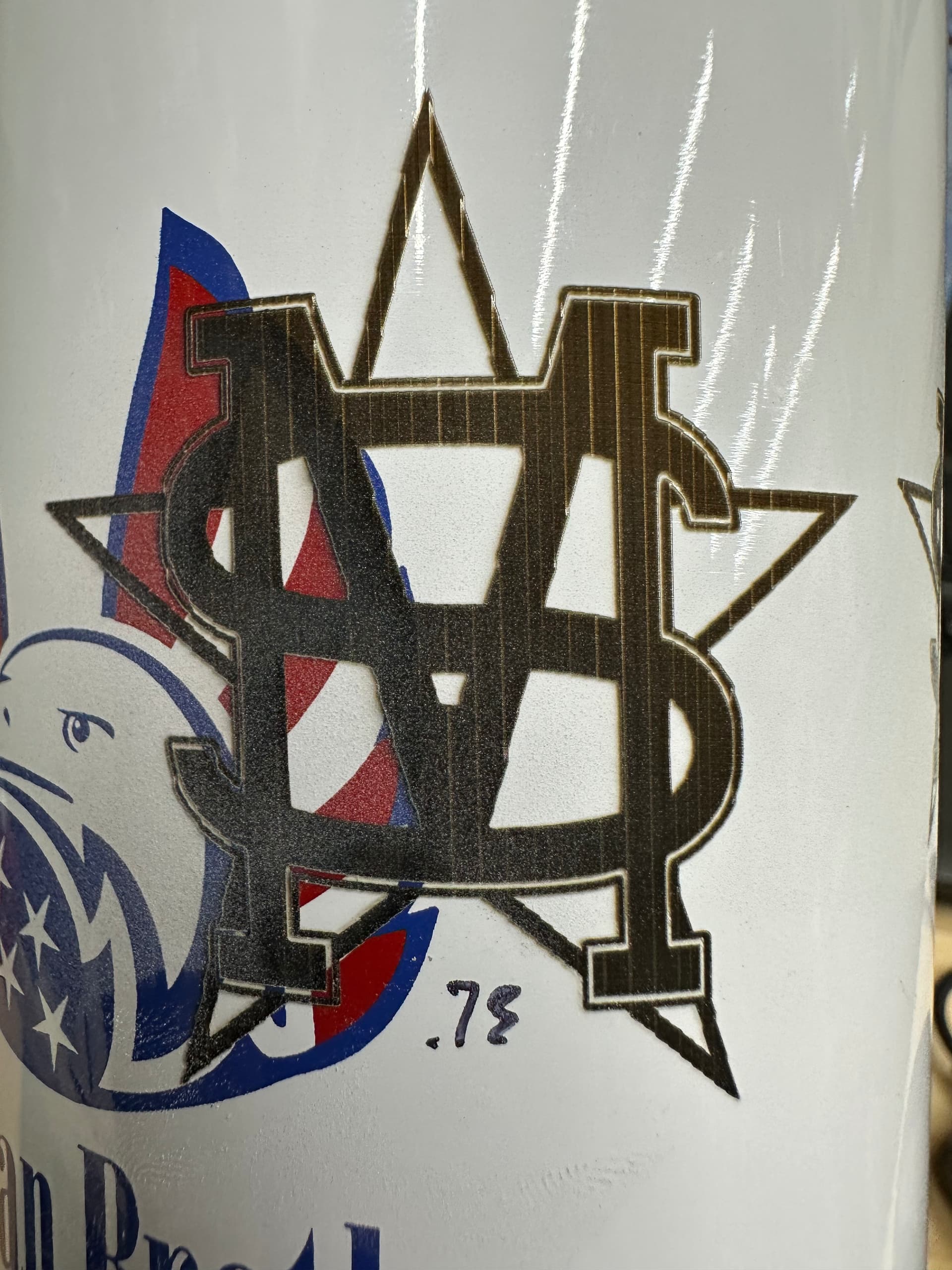
I tried multiplying by x35 to get a split size of .73 and again by x45 getting a split size of .94. Results got more choppy as I increased the split size. I then tried dialing it back by multiplying by x10 getting a split size of .21. This was probably my best result but still getting some waviness which bugs me.
The saw tooth is almost always from steps not set correctly, or diameter measured incorrectly. The software thinks the surface moved further then it actually did. Like an unintentional overlap. . Not saying that is your problem but makes me curious. If it was me, I would mark a 20mmx20mm or 30mmx30mm square on the tumbler and measure.
The largest one (.94) really shows this.
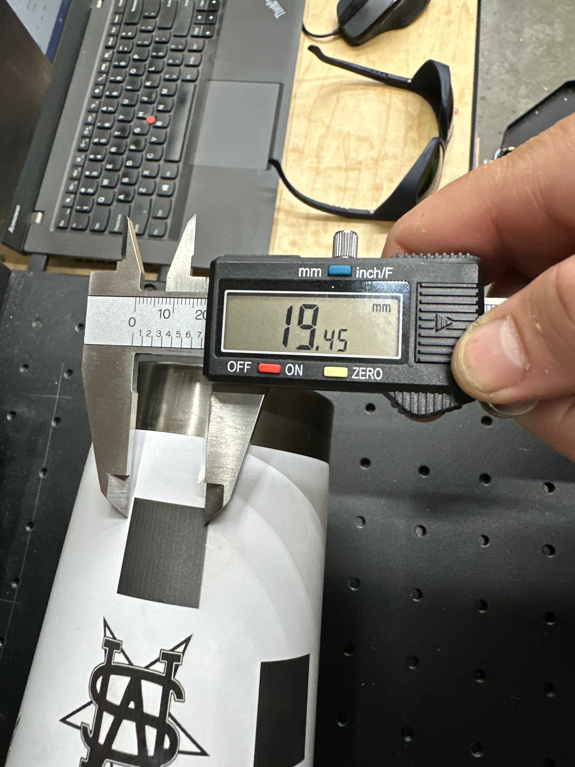
I drew a 20x20mm square and engraved on the bottom of the cup, remeasuring the diameter (76.73mm) again of course which gave me a circumference of 241.054mm. 241.054/12800= .0188x25=.47 which I used as my split size.
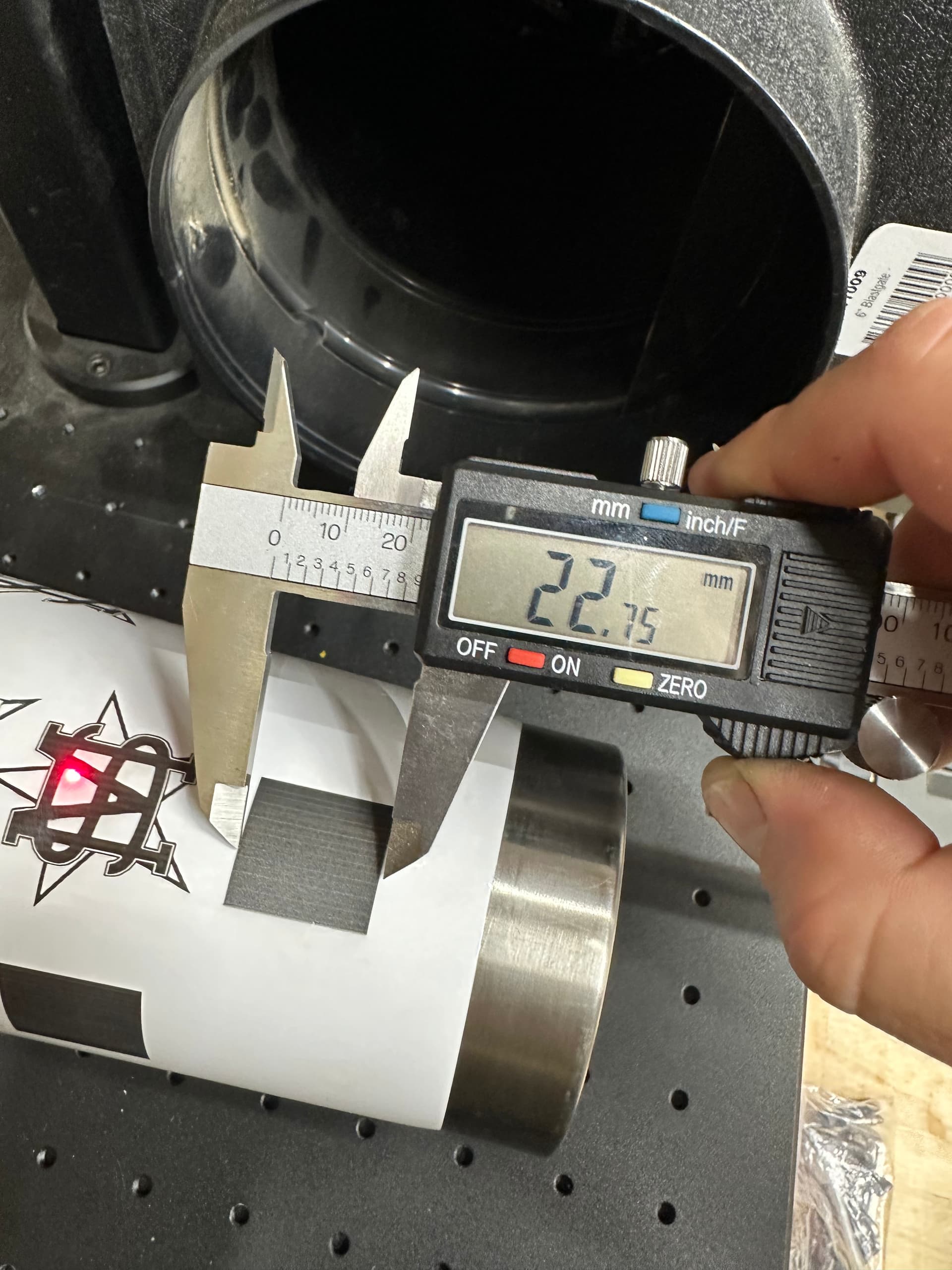
20x20mm square engraved at 22.75mm on the x axis and 19.45mm on the y axis.
So surface of the tumbler is moving only about 85% of X, and X is way larger then it should be. Also, the 22.75mm is way off what it should be making me think your calibration is off.
I would go back to flat and run the 20x20 again, see if that is correct.
The output center corrects for the rotary being off center of the galvo head, if the galvo is directly centered, a 200 lens should have a 100 output center. I don’t think that is your issue, just curious how you determined that.
You could also, as an experiment, set your steps to 14971 per rotation and run a test (22.75/19.45*12800) This should give you a 22.75x22.75 square on the tumbler.
Calibration was definitely off…went through everything with a fine tooth comb utilizing this great video from Lightburn. I’m in much better shape now. Re-ran my flat test and came back with perfectly square rectangles. Tried this test using the rotary and same thing, rectangles on the tumbler are looking good and the proper size I’m requesting.
I’m going to be turning in for the night now but I noticed something else curious during this whole process. While in the rotary setup menu I pressed the test button in the rotary axis menu and watched/listened/felt the rotary turning 360 degrees. I feel physical vibrations from the chuck as it’s turning and it’s making a grinding noise as well. It’s hard to tell in the video but I can feel the chuck shaking if I put my fingers on it while it’s moving. I went through and made sure every screw was tight and double checked that it was secured to the laser bed well. I wonder…