Hi,
My issue is the following:
The point of the laser is not “infinite thin” as the software considers.
This means while using any fill to fill a shape there is basically no offset applied and the actual fill is wider than the one in the software. Here is an example. I have a Sculpfun S9 diode laser. Every diode laser has a rectangular shape. This means if I burn a simple cross one of the lines will be thicker than the other. Mine has 0.1mm x 0.2mm roughly.
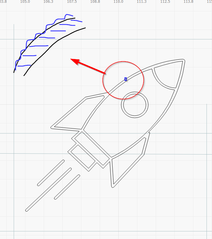
Let’s see a situation when I engrave a small 10mm x 10mm logo with horizontal scan lines:
As the software considers the point of laser to be infinite the vector is traced on the outline with no respect to the width of the laser. This causes the following situation
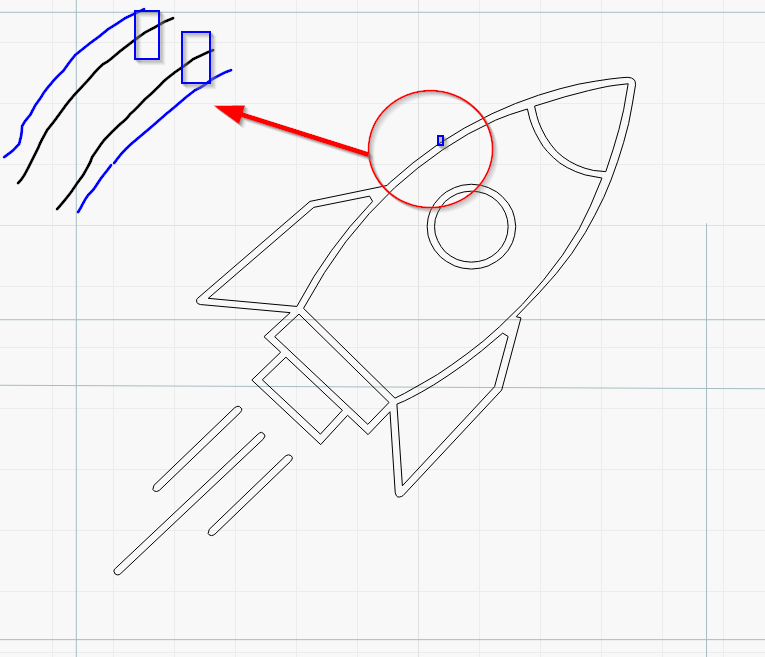
I can choose from jagged edges or shapes that are not true to their vector size:
A solution would be to apply 0.05mm offset to every shape. However diode lasers are not square usually so applying offsets becomes very cumbersome.
This should work similarly to CNC software where you define the tool size and the software remains within bounds.
I’m open for any suggestion to overcome this issue. I’m especially looking into using offset fill, but as it works now I rather not.
AFAICT, the LinuxCNC G-Code dialect allows only a provision for the tool “diameter”, rather than a rectangular extent, so it’s quite similar to the LightBurn Offset tool’s operation.
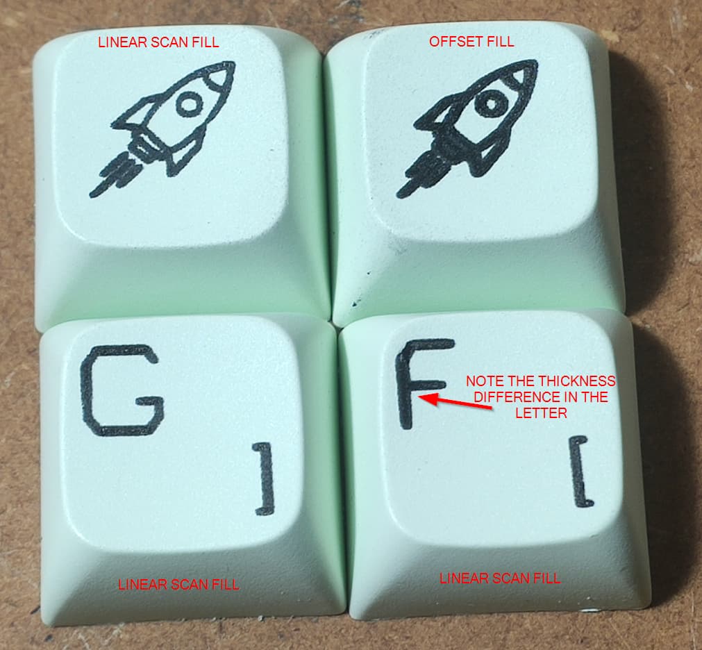
Kerf is close but it does not solves the issue of the beam has different dimension in x and y. Even if I offset the shape with let’s say 0.1mm (as the beam is 0.2mm high) and use fill+line engraving with kerf the letter F for example will have two different sized part for the vertical and horizontal. Unfortunately this is not good enough for my current application.
One would say “buy a better laser” but I believe this is something that could be solved in software as the market is flooded with diode lasers and most of the people are using these.
Dot Width Correction may come closer to what you want, because it tries to reduce the X dimension more than the Y. How well that works in practice with a rectangular spot will definitely require some experimentation!
If you get your line interval tuned-in and do a conventional scan this issue will largely be moot. This is really only a factor because of using offset fill. Offset fill has far other “issues” beyond the handling of non-square laser dot that make it non-ideal for what you’re trying to do.
You may want to consider a different strategy:
Create 2 sublayers
First sublayer does just the outline of the shape
Second sublayer is a conventional fill
The outline may serve to keep the fill within the lines.
And again, I’d highly encourage you to run some tests. You want to focus on 2 things:
Make sure you’re getting the minimum burn to eliminate any overburn. The lowest to create a clean mark as fine a line as possible.
Once you get the proper setting for the finest line, run an interval test to make sure your line density is optimized.
Then attempt a traditional fill or the strategy I listed above.
I have one more idea: offsetting the shape and scanning with 45deg lines. At least for letters it could be a bit better in theory. I will look into dot correction also @berainlb
what you see on the keycaps is pigment (toner dust) melted on them with 5% power. This is the minimum strength where it sticks. It is not a burn mark, i believe this case I have nearly zero burn. All the pigment that sticks has been touched by the beam. The lines in the left rocket keycap are extremely fine and all the jagged edges are from the square laser beam
The machine might produce faster and more accurate results if you rotate the image (and keycaps!) by 45°, then scan along the X axis as usual. You’re surely using a fixture already, so making one with rotated sockets should be straightforward (said the guy who doesn’t have to do it).
Involving both axes in the scanning motion forces the machine to run at the slowest of the two axes and introduces more mechanical vibration. Simplify! Simplify!
I’d still encourage you to run some tests to come up with ideal settings and interval. By definition the offset fill will have overburn at least along one axis.
Is the .1mm x .2mm dot sized based on what you’re getting with the toner on this material? Or is that based on something else?
Run lines tests at 0, 90, and 45 degrees at varying power until you get the finest line possible. Ideally this would be done on the material you plan to burn to. The sculpfun s9 laser module should have one of the smallest dot sizes available. There is of course quite a bit of manufacturing variance.
If you haven’t already, do a focus test and make sure you’re absolutely as sharp as you can get.
At the scale you’re working at it’s possible that the variance in keycap height may also be playing a factor.