I’m by no means a profession embedded programmer. I’ve done some and now hack on whatever MCU fits my projects. STM32s have shown up all over and moreso in these cheap Chinese machines, hence were we are.
I had uninstalled CubeIDE from my machine and went back to see if I could find an earlier version of the True Studio and was surprised to find so much CubeIDE and then the list which said not to use the True Studio for any new work. Not harping on you, just giving you feedback on what I found on the ST site so you know what’s going on.
I went back to the grblHAL installation document and they mentioned using CubeIDE so I reinstalled that. I then followed the instructions and built it. I got 3 errors and all were related to the output not fitting the program space of the 103C8. So I changed the build from DEBUG to Release and I turned off USB_ENABLE and that now fits.
I will now need to fit a FTDI board to the tx and rx outputs to see if indeed this is working. It is a tight fit at 96.9% of program space used but that’s a pristine git repo install so surely there’s something to trim off. I changed the build optimization to Os( optimize for size ) and got 87.0%
You’ve been in this way more than I and I’ve yet to figure out what MX is. From how I read what grblHAL was I thought it was just a refactoring of the code so the hardware specific stuff was separated and clustered together and all the generic grbl stuff out in core. So not sure if a different IDE will make tweaking this any easier or not. It is at least the IDE the developers of grblHAL recommend.
So you are making a good progress. So far all this easy stuff.
I’m waiting to see how you will resolve PWM move/allocation. That was a head scratchier for me that I’ve spent absolute majority time on.
MX is HAL code generator. These ARM MCUs have so many peripheral options - it is inhumane to do it manually. So MX generates init code to setup all HAL registers, basically configuring chip hardware interface to be ready to accept your code with specific calls to specific peripherals. Output of MX is project template with banks for user code and all setup code already filled.
This is my basic understanding of it.
I guess for super simple project it is possible to dig reference and setup necessary peripherals manually. Even simple IOs must be defined, by HAL/MX or somehow else.
MX translates HAL to basic human language with presentation interface that can be interpreted by hardware and software engineers, reducing learning curve. It is still pretty deep. I’ve spend a few hours setting up new project for JL1 hardware. Eventually went nowhere with it and I’ve abandoned it. But learning it is useful anyway. I might use it int the future.
103C8 is 64K, so if you fit - you should be good. Prune it a bit, make room for boot loader.
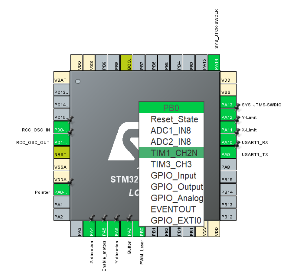
If you want to go that way: you have only x2 timers available at B0. TIM1 is original but different channel. And I believe it is used for other things. This pileup inherited from original GRBL source with fewer timers. TIM3 - you need to check if it is not used anywhere else and then steer spindle2 to it. You may as well go level down and reroute spindle1 to TIM3. That is if TIM3 not used anywhere else. Then you need to HAL init TIM3, meaning to regenerate HAL (not for me), and then add GRBL code to load it with proper values and hook it up to the code.
I think there are available timers, maybe even TIM3 is available, chip has total x4, but this is not my way.
So there are not many options.
I chose to use CH2 of TIM1, and most edits being in HAL. Well, because it is N channel - I had to invert it in software.
Just to be sure @LsrSal you edited that chip graphic and added the JL1 signal names to the pin locations? I’m going to ask for guidance on how to proceed with creating a new board definition for grblHAL and figured this picture is worth a few thousand words.
Doug,
I did not do any graphics edit here. This is is a screen grab of my effort to create new configuration for JL1 in Cube MX.
This my effort is not complete and still took a few hours. Trying to reintegrate this into any original source - I’ve failed. So I have abandoned it.
But this is a good illustration of what MX is: it is automatically offering available hardware facilities that can be selected and configured by HAL. This is the first step. Then you can define parameter for each pin, then whole system clocking. Then you generate project template.
Yeah, even with simplification of HAL configuration by MX - it is still very heavy task. JL1.ioc.txt (5.2 KB)
wow, I just was not believing there was going to be a tool like that which would be compatible with grblHAL since it is not a STM32 dedicated project and supports other ARM targets. But maybe Cube MX is target agnostic. You definitely showed me, and told me a few times, that MX template stuff is where all the magic happens and it’s a PIA.
Maybe it will integrate better with grblHAL vs the grbl32 codebase you were starting from. Thx for sticking with it.
update: I found the ioc file in the default STM32F1xx driver of grblHAL and went to open it in the CubeIDE and it loaded that MX viewer it seems you got that image from. Odd that I see no PWM references but since it’s for a CNC3040 it might be doing serial to a VFD for control. I’ll keep looking and reading.
Do you use the internal header to load your programs or is it via the serial port?
I’ve upgraded the cenoz via the ‘upgrade’ program and it talks to Lightburn, but I haven’t opened it up for a hardware addition of pins for the st-link device…
I assume the bootloader is for serial communications to lightburn or the external application?
I’ve used micros for many years and never load a bootloader on them unless it’s something that is going back into an Arduino board and it needs to talk over the usb…
I also installed the ‘cube’ on my Ubuntu box as it appeared to be the latest and greatest.
Doug,
Now I’m afraid you are loosing traction, maybe not. But lets repeat what we know, in case some do not, just to sync:
“HAL” (Hardware Abstraction Layer) is general term.
Cube is tool for ST’s STM32 family only. It is NOT processor agnostic (even if underlying environment may be agnostic). It is not aware of GRBLHAL nor specifically compatible with it. Compatibility here is the fact that GRBLHAL has option for STM32, and STM32 code can be developed in Cube.
In GRBLHAL, that “HAL” part is as I understand is expressing modularity of the code for various boards/processors. In Cube/STM envriment HAL is chip’s peripherals configuration.
Jack,
It is discussed above, but I guess this thread is also become runaway. Here is the summary relevant to your question:
I’m trying to use factory boot-loader. I’ve discovered that firmware is scrambled (specifically not using work “encrypted”). see above.
If successful, unknown offset for the app can be tried as flash on this board can be loaded only in 1K chunks. So there is about only 20 possible offsets. Can be tried manually.
It is separate effort to develop the firmware and to be able to load it with factory boot loader, that would be nice.
Doug practicing to develop for Blue Pill board. Then figure out what next.
So see my two screen shots above and try to crack it. Once we have this scramble function - we can preprocess our firmware and load it with factory boot loader over serial/USB.
If you are interested - keep your machine on JL3 firmware till further notice. You can load my latest with working homing on your first machine, it does not have boot loader anyway.
I’m using the ST-Link interface(4 pin header) on the end of the bluepill for firmware uploading.
Someone(you?) had shown a picture of the JL1 before and I saw the empty ST-Link header pin holes. They probably used a bed-of-nails test fixture and programmed the chips that way. But I suppose they could have programmed the raw chips before assembly and solder flow too…
The bootloaders are often used for ways to upload new firmware. I don’t know how the Arduino bootloader works but as you noticed it uses the same serial port and there must be some special handshaking which tells the bootloader to either accept a serial stream which is the new firmware or else just hand off the boot process to the fixed address where the firmware starts.
It doesn’t have to be the same serial interface as the running firmware uses. The Ortur bootloader creates a little USB HiD drive of 64K in size when it’s kicked off. If there’s a file named firmware.bin in the memory location on next boot, it copies that file to the firmware start location, deletes the file and reboots. When it finds no firmware.bin file it proceeds with normal firmware booting.
Normally we just burn firmware directly to the base starting address of the mcu and they do their thing for us. But the more we expect to update firmware the more handy it is to have a bootloader to help the consumer.
Sal, I went looking in a bunch of the grblHAL repo at the other boards and you are correct, I only saw the CubeMX config file for STM32 boards. The others have their own unique ways of defining the hardware pin configuration. Probably more like the standard pins.h was for Marlin and probably others.
We are very close to being on the same pages here. I’m learning.
Sal, I just connected up a 3.3 FTDI to pins PA9 and PA10 on the Bluepill since they are listed as the UART1 pins for the grblHAL F103C8 driver I’ve compiled and loaded. But I see no output on reset. I was expecting to see a GRBL header echoed so I’m not sure yet my firmware if functional on the Bluepill.
If I were to flash your JL3 firmware to the Bluepill, where would I expect to see GRBL echoing out the same Tx and Rx pins?
Thanks, I will find your V2 firmware and give it a try. Yup, found in http://github.com/LsrSal/DEE_JL1/Firmware and I saw the grbl dump out pin A9 as expected so something is amiss with my grblHAL build.
BTW, I’m not starting from scratch, still using grblHAL STM32F1xx driver from the grblHAL repo as my starting point.
@LsrSal I finally got to where the Bluepill will run grblHAL on its own. I got incircuit debugging working with the ST-Link and could run that way but could not get it to run on its own. Then I tried downloading STM’s CubeProgrammer and it loaded the 111K image and voila the Bluepill was running via USB power with my FTDI connected to pins A9 and A10.
So I think it’s finally time to try figuring out how to move the PWM/spindle to PB0.
update: grblHAL dev recommended to look at preprocessor directived used for the 32F4xx driver and I’ve ported that to the 32F1xx driver. I now can define if we’re using port PA8(TIM1_CH1) or PB0(TIM1_CH2). @LsrSal does that seem right? It does compile without errors.
I cannot say right but I see nothing wrong. JL1 has laser on B0. So however you produce spindle/laser PWM on B0 should be good. If you manage to control PWM on that pin - all set. The rest is peanuts.