I finally did it!
So I’ll leave here some notes and an explanation of how it was possible.
.
Notes to take into account:
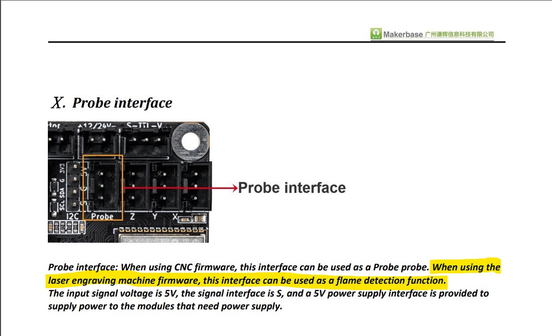
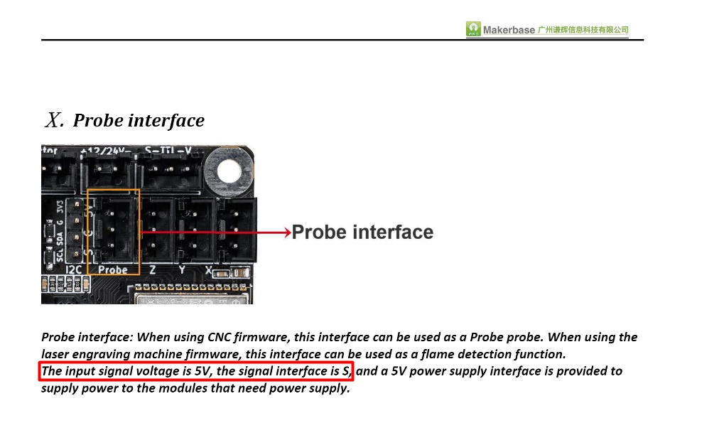
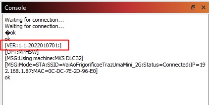
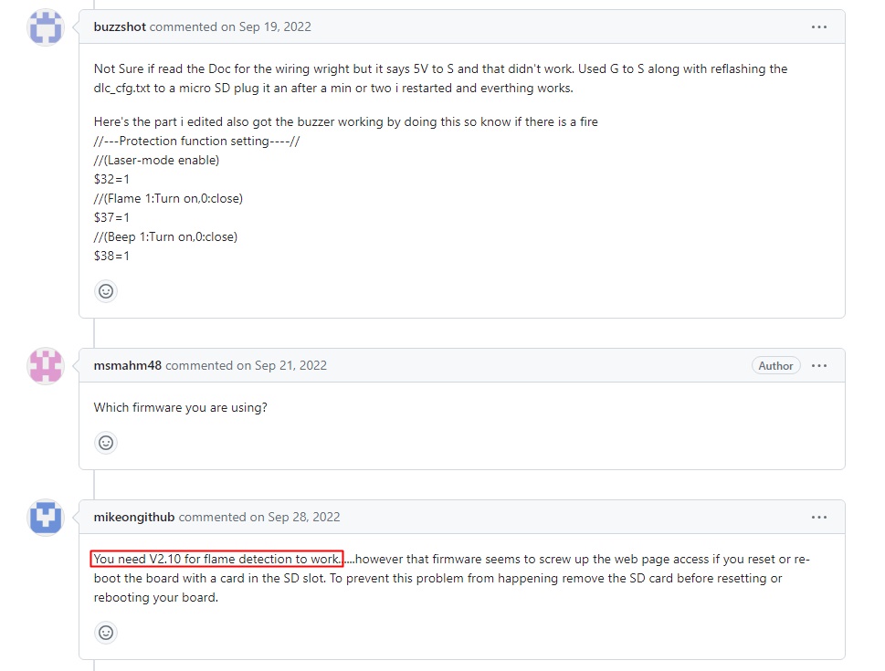
1 - Only firmware V2.10_H35_2022_0621_N_ZX_001 supports the “Flame Detector” function through the signal on the “Probe” port.
(Moderator Edit: Corrected Typo at Kuth’s request
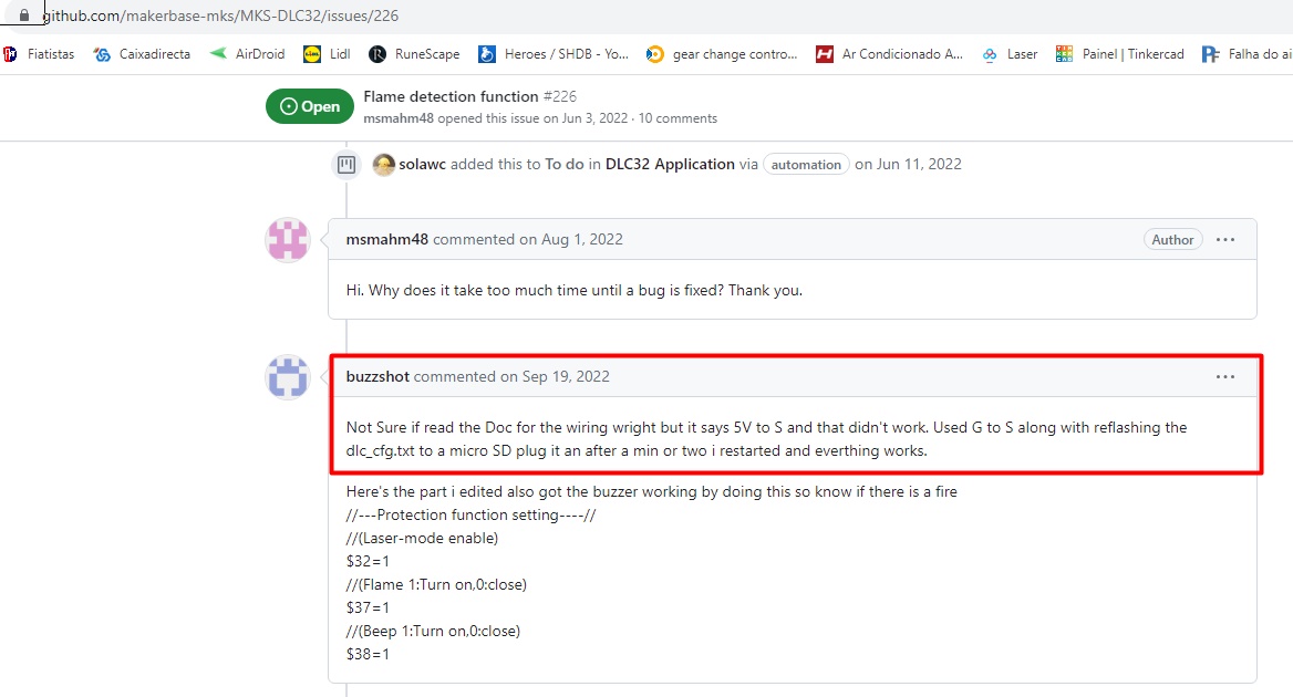
Technical reference: Flame detection function · Issue #226 · makerbase-mks/MKS-DLC32 · GitHub)
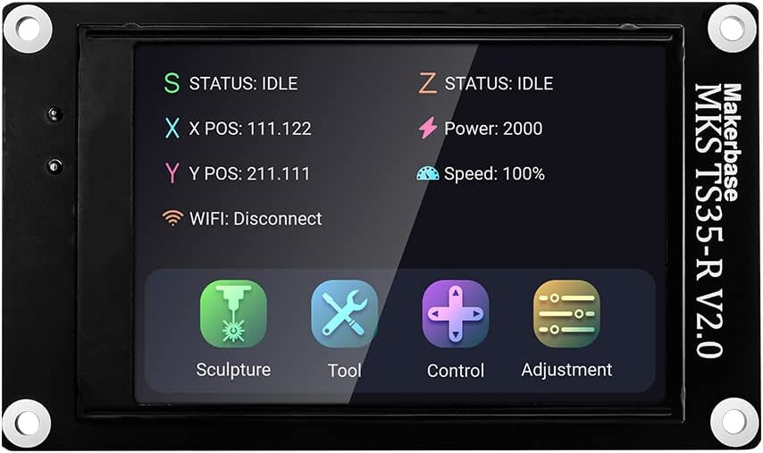
2 - This firmware is intended for boards with a 3.5" display
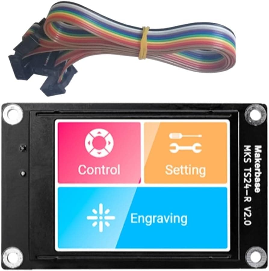
however, the board works even without the display. Also works with a 2.4" display
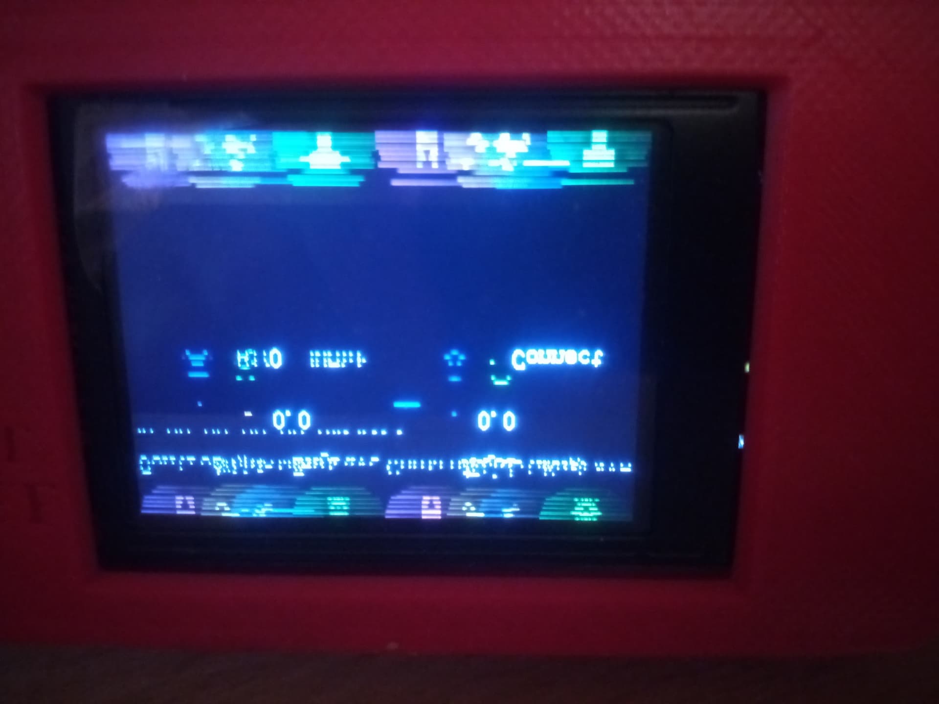
but it becomes unreadable due to the firmware settings being for 3.5"
.
3 -
Use a flame sensor with output at 0 in case of alarm. (positive in normal mode)
Otherwise it will have to be changed as happened to me. (Image at the end of the video included in this thread)
What was done:
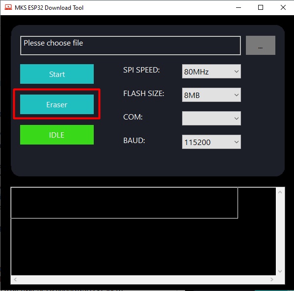
1 - With MKS board connected to computer, through the software MKS Tool
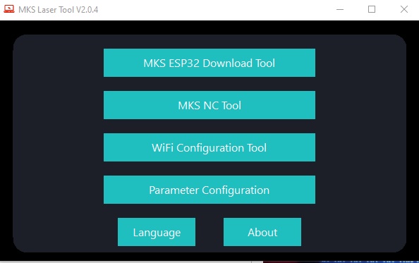
select
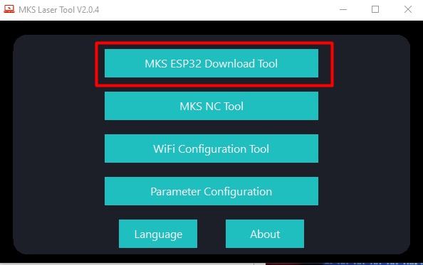
then select
and delete de existing firmware.
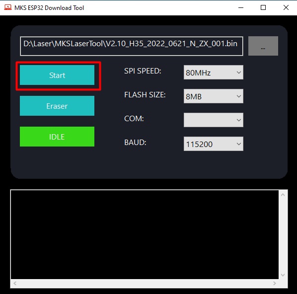
2 - Then install the new firmware.
Select the new firmware file
and hit Start
When finished reboot the board.
3 - Copy dlc_cfg.txt file to a 4-16Gb SD card FAT32 formatted.
Open the file and correct the parameters $37=0 to 1 ($37=1) and $38=0 to 1 ($38=1), save the file. ($37 enables de flame sensor, $38 enables buzzer)
Insert the SD card into the slot on the board and reboot again. (If you have a 3,5" display connected you will see some information running.)
(I didn’t include images for this step because I didn’t have the display yet at the time.)
NOTE: Parameter $37 is not visible through software. Only configurable through the dlc_cfg.txt file
Turn off the machine and correctly install the flame sensor to the “Probe” port.
Turn on the machine and run a test. It should work fine.
Have a lighter on hand that lights up better… 
More details at GitHub forum where i discuss the most of the issue.
I hope I can help someone so that this topic becomes useful.
Special thanks to @JohnJohn for reopening the topic at my request after more than 2 months of inactivity in this topic.
This topic was inactive but the reason for this topic was not.