For a small symbol, I need to highlight the contours

Hello again. I need to discuss something I’ve been struggling with all weekend. I’m making a logo for coasters, but I can’t seem to get the Czech lion symbol to stand out. I always get just an outline. The lion is designed in reverse, with two parts of the same color overlapping. The file is attached.

leon.lbrn2 (254.5 KB)

You can see what result I get here:

How it should look like:

thanks for help.

See if this does what you want. I did a .05 outer offset on the lion and changed to a different layer then deleted the unwanted lines. Changed the outer shape to the same layer as the offset. Set that layer to fill then added a line after fill sub layer. Leave the lion layer set to line and that should give you detail without engraving. I think tryiong to engrave those thin areas just aren’t looking good on something this small. You will probably need to speed up the line layer so it’s not too deep.
leonedit.lbrn2 (271.8 KB)

1 Like

Take your pick.
leon1.lbrn2 (189.6 KB)

1 Like

Thanks guys, I’ll give it a try and let you know how it looks.

It’s very small and detailed, so it’ll probably need a higher speed and engraving rather than wrapping?

CO2 are not first choice for fine detailed work.

… I definitely don’t think so :wink:

made with K40 and OMT 60 (CO2-Laser)

Your saying a CO2 can equal a diode detail?

…better :wink:

1 Like

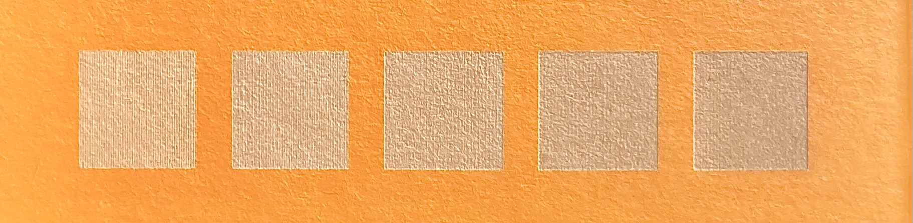
If all the other ideas fail, you might check out the speed you’re attempting to do this and also take into account spot size of the machine. Interval is very much related to spot size.

A shorter lens will give you a smaller spot, all other items being equal.

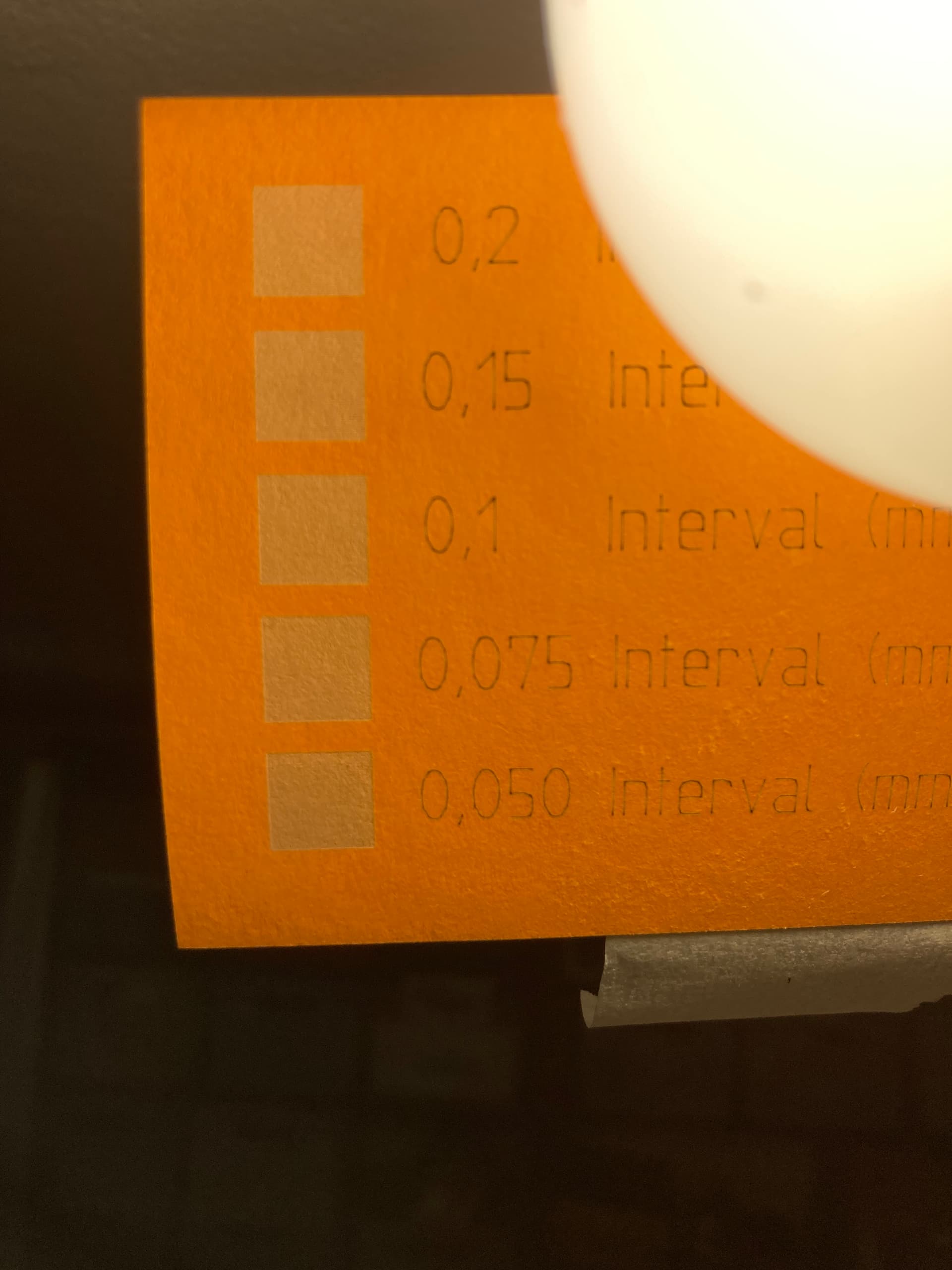
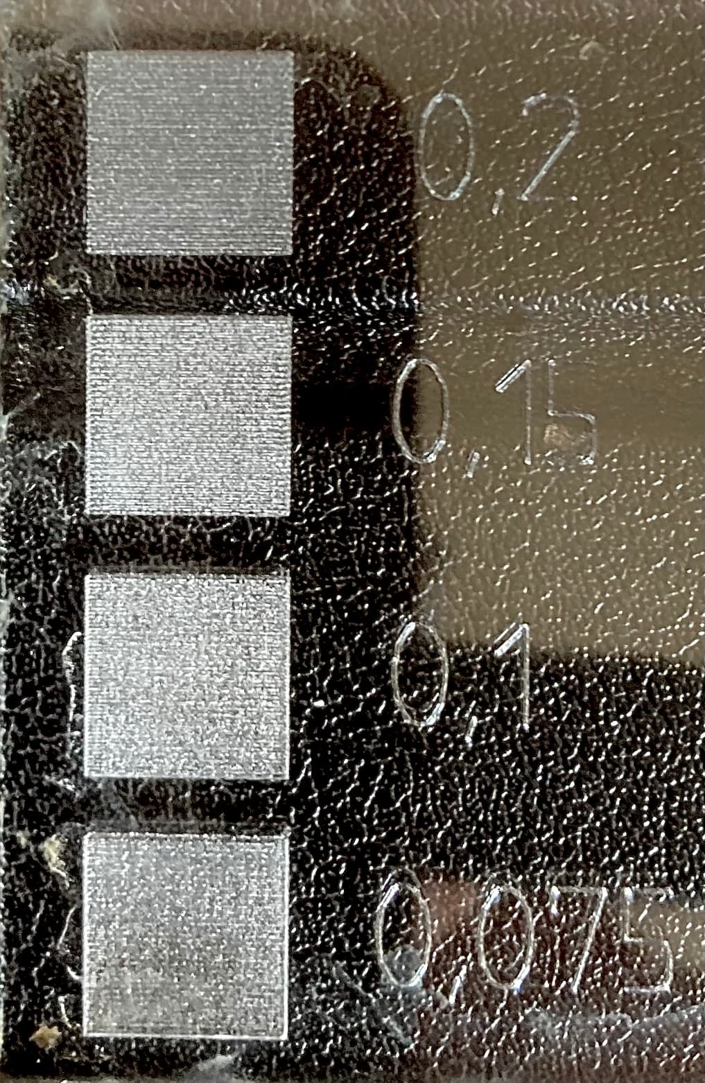
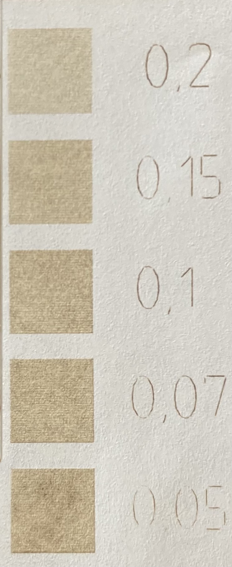
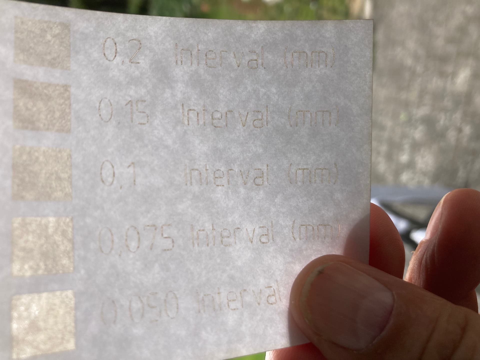
Most of these come with a 2" lens (50.8mm) that produces a spot size of about 0.205mm, based on a 5mm input beam. You will find it difficult to produce an image with any resolution of greater than ~124dpi (0.205mm interval) if your spot size is the 0.205mm assumed here.


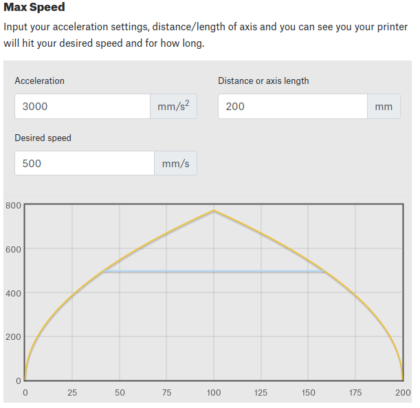
If you are doing small vectors as some have suggested, you likely can’t reach such a high targeted speed in such a short distance.

You can see the value set and the distance required to reach this speed, which is almost 50mm. If you are doing an image or fill, this will be the overscan.

The acceleration values on your machine could be different, resulting in different results.


Your glass tube/lps has a response time, usually, <= 1mS to reach 90% placarded voltage.

Worst case, is that at 1000mm/s, you cover the 1mm distance in 1mS. Turn it on or off, requires 1mS or 1mm in distance.

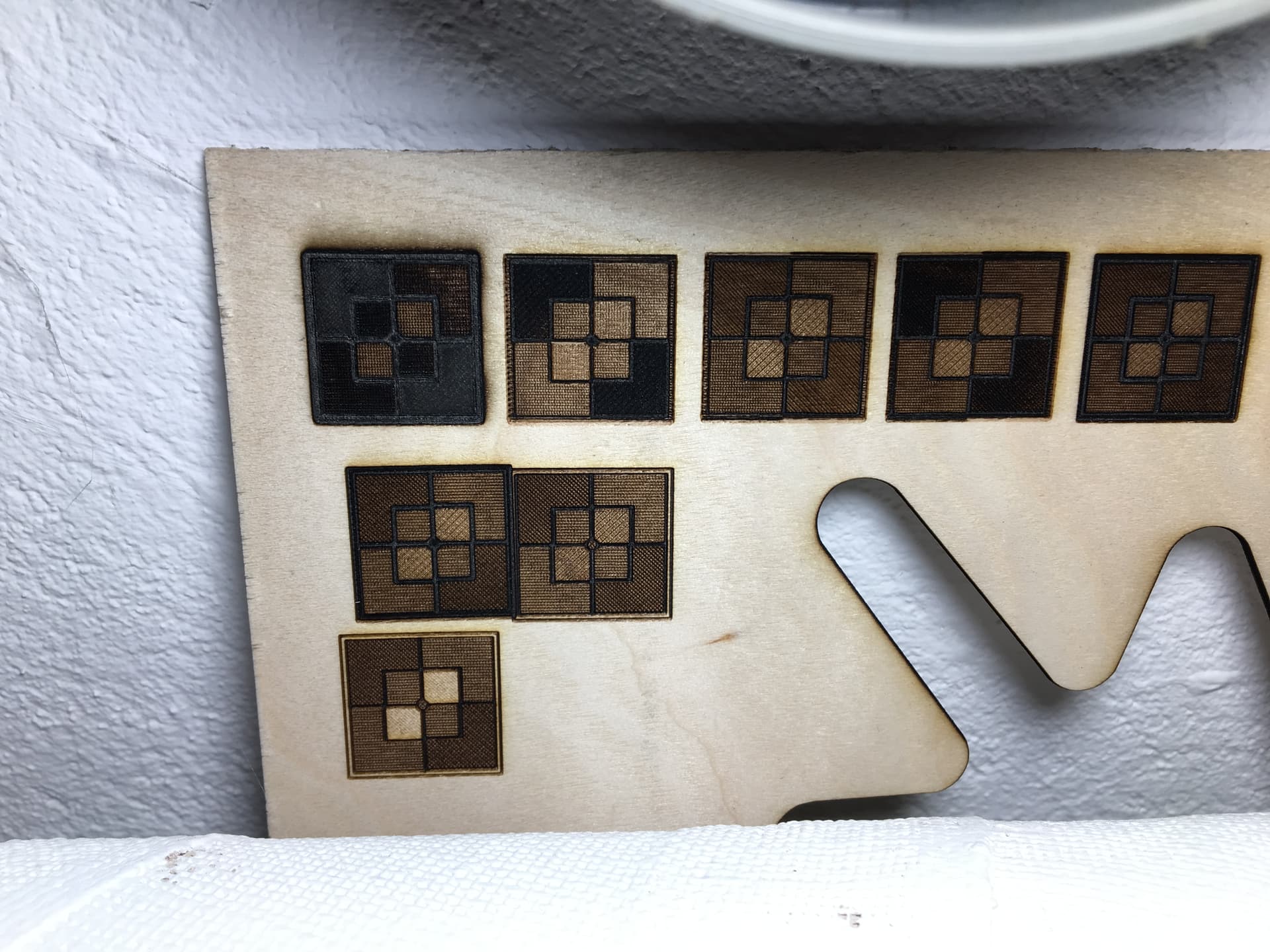
The best resolution you can expect to achieve, and still be in control of the lps is 25.4dpi.

Slow down to 500mm/s and it doubles the possible dpi to 50.8. At 250mm/s, it again doubles it to 101.6dpi

My machine will run 1650mm/s, but most of my engravings are using speeds below 300mm/s.


If you use minimum power, you might want to check your Ruida Start speed to ensure it’s low enough. If not the output when the speed is <= to the start speed, then you will only get minimum power.

Good luck

:smile_cat:

An easy way to determine one’s machine’s option in relation to Spotsize is to use LB’s built -in, “interval test”. It will give you a reasonable precis indication of which line spacing you can use optimally.
With my 2 "lens I end up between 0.075 and 0.08, ie spaces between the lines are not visible anymore. You can easily choose 0.05, but then the lines will overlap, it will spend extra time and has no posed effect. 0.1 will give (me ) Spaces between the lines, it is also not desirable.
My speeds are generally relatively conservative/moderate and depending on the task and size between 200-300 mm/s.
(all other dimensions in mm)

This is pretty incredible. I can’t get that small with my compound lenses… do you have a beam expander?

These are in the 340dpi area, about what a diode does.

Any secrets?

:smile_cat:

1 Like

Denmark is on a different metric system.

1 Like

No Jack, standard 2" lens. Unfortunately I don’t have a microscope but when I do my line test it is quite clear to me when I get the optimal distance. It is possible that theoretically a line distance of 0.075 (0.08), is physically not achievable with my gear, but subjectively optically, with 0.075 mm I have the most balanced interval without gaps and without (visible) overlaps.
I don’t always use this line interval, I play a lot with angles and line spacing for the different projects.

Try looking at my test image and tell me which step is the most homogeneous in your eyes.

As it moves to the right, it looks better… What material is this?

:smile_cat:

It is heavy paper

In no. 2 it is acrylic

No.3 er tynd paper


Just tossing my prior work in the ring here RE: CO2’s for precise work

3 Likes

With the exception of acrylic, I like the 0.20mm interval…

:smile_cat:

Everything is subjective but to be free from seeing lines, I need my machine under .1mm, 0.08 (0.075) is my choice.

Spotsize is a little different, but as you have also touched on, very dependent on power and speed.
The discussion itself was initially probably about diode versus CO2, here is my personal ranking, 1st place - 40W K40, 2nd place - 60W OMT, last but certainly not bad - here comes my 5.5W diode laser. If the diode was square, it would possibly have been awarded 2nd place.

Do what you do to get what you want… so I’m OK with whatever floats your boat. Was just curious.

I have always like the co2 best, although the fiber is a lot of fun…

:smile_cat:

…I really want to play with such an animal