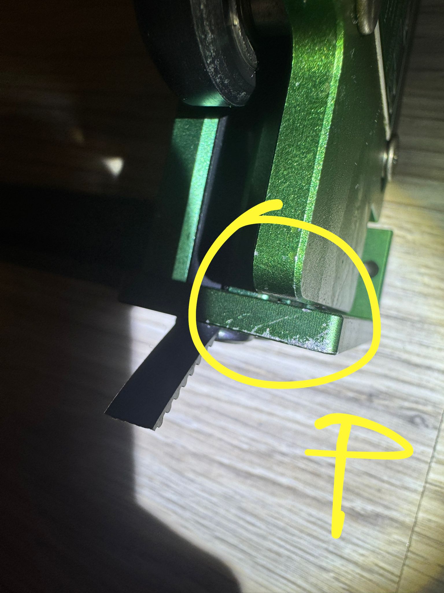
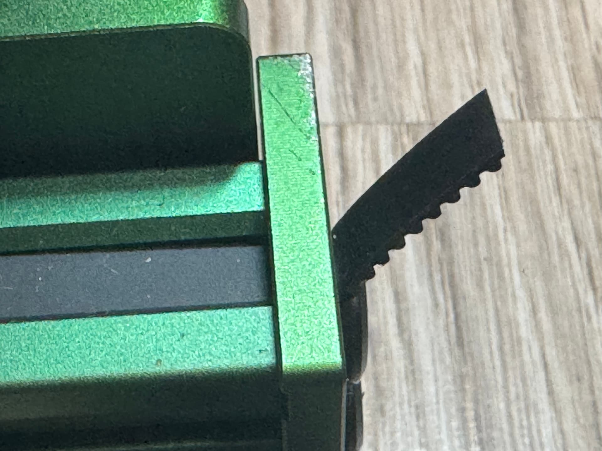
Hi, for several weeks now, I’ve been trying to figure out why my laser cuts oval circles, and the start and end points of the circle don’t connect. I’ve checked all possible areas for looseness, and only today did I notice that the carriage on one side doesn’t reach the frame. When I push it with my hand, it bounces back. Could this be the reason for the distorted circles? How can I adjust it, as I’ve run out of ideas? I’m attaching photos of the issue and how the circles are being cut.


I have the same mechanical problem with my Neje Max 4. But for me the circles are closed and round. Have you ever calibrated the travel paths of the axes? If they are not exactly the same, at least a closed oval should be created. But that’s not the problem you have. Is your Z axis vertical?
I calibrated the laser several times in LightBurn and checked the alignment of the laser module with a square. The module is slightly misaligned, but a friend said it shouldn’t affect the precision of cutting circles. The issues with cutting appeared suddenly—everything worked fine for several months, and then one day something changed. Could you share your settings, such as the acceleration parameters for the X and Y axes? Maybe I have something misconfigured. ![]()
Enclosed you can find my settings. Please note in the moment a play around the “homing feed rate” and “homing seek rate”. This values are not original.
Maschineneinstellungen.lbset (6.0 KB)
You can import over: EDIT\Machine Settings
Are the belts all properly tensioned? Somehow it looks like a step loss.
I used your settings, but it didn’t improve the circles. As for the belts, I have adjusted them multiple times on the Y-axis. I also moved the Z-axis further away from the board, and now I’m wondering if it’s normal that the laser beam left a narrower mark on the left and right sides of the to the top and bottom.

circle compared
The circle usually needs to be even.
I can think of 2 reasons at the moment:
- The surface is not level. This is often the case, for example thin plywood has dents.
- The Y-axis is not level in a certain area. This changes the distance between the lens and the board.
Diode lasers have a rectangular spot, so they tend to have a wider kerf along one axis. In your machine, the long axis of the spot is parallel to the Y axis.
Unfortunately, that’s not “fixable”, because it’s inherent in the semiconductor producing the laser beam. This discussion has some background:
Well it’s probably not a problem so far since the laser has been cutting the wheels correctly for several months , I’m very anxious to eliminate the distorted wheel and for it to close correctly, but I still can’t locate what could be the cause of the oval wheels, I’ve already checked the belts, pulleys, eccentric screws a dozen times and nothing has changed. Is it possible that the X axis is to blame ?
Yes I came across this thread earlier and saw a video on yuoutube addressing this topic. But does it matter in my case if the laser has been cutting the wheels well for several months ?
Ah, that’s new news.
That suggests the focusing optics or a laser diode has suddenly gone bad, which will change the spot shape and lower the output power.
Take a look at the Wall Test section of this guide to Scuplfun mechanical adjustments:
Check the lens / optics for damage, and, if everything looks good and you can do it safely, light up a wall. The overall shape should be square-ish and the number of spots / stripes should match the number of laser diodes in the head.
@bernd.dk or @misken may have additional suggestions, as they’re much more familiar with diode lasers.
Thanks for this trust ![]() , but my experience with diode lasers is from before diode lasers with multiple diodes were introduced. So my part of the information is in this case only of a general or theoretical nature / value and will hardly be part of the solution here.
, but my experience with diode lasers is from before diode lasers with multiple diodes were introduced. So my part of the information is in this case only of a general or theoretical nature / value and will hardly be part of the solution here.
One of the most experienced and professional diode people is definitely @gilaraujo , if you are lucky he will find the thread and help.
Thanks @bernd.dk
I am inclined to think this is mechanical and possibly based on the squareness of the frame rather than the belt tension.
Neje frames are prone to get off square quite easily.
The simplest process I found to get them back to the square is to loosen the sprocket on one of the Y-axis sides - move the axis manually to the top or bottom - press both sides against the frame, then tighten the sprocket again.
Having someone help on this process really helps.
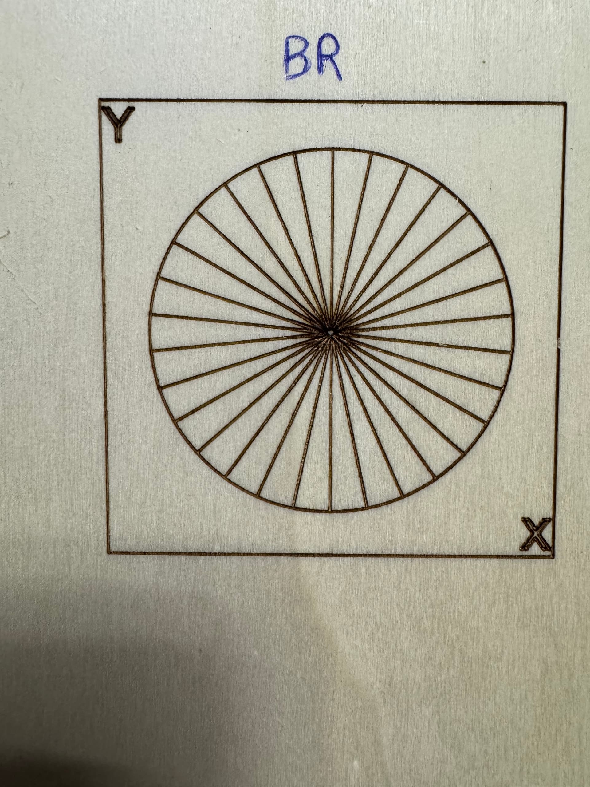
Then @wzw97 try to run this pattern - but move it across the 4 corners of the machine
You can run it on a bit of spare wood. make sure to mark the corners
FL BL FR BR (FrontLeft as short) as well as dead centre.
We want to see if the issue is more accentuated in any of the corners
Dot Test with Angle.lbrn (46.3 KB)
(adjust power output and make sure to focus- we want as crisp line as possible)
Take Pictures if possible for the class ![]()
To me, it looks like a mechanical issue as well. Though, throughout the Facebook groups, I recently got many reports of the latest LB versions behaving weird occasionally. I would also recommend to download the latest 1.6 version and check using this as well.
I did a test with 4% power directed at the wall from about 1m. This is what it looks like. The Neje Max 4 laser supposedly has 4 diodes, so shouldn’t there be 4 beams on the wall?
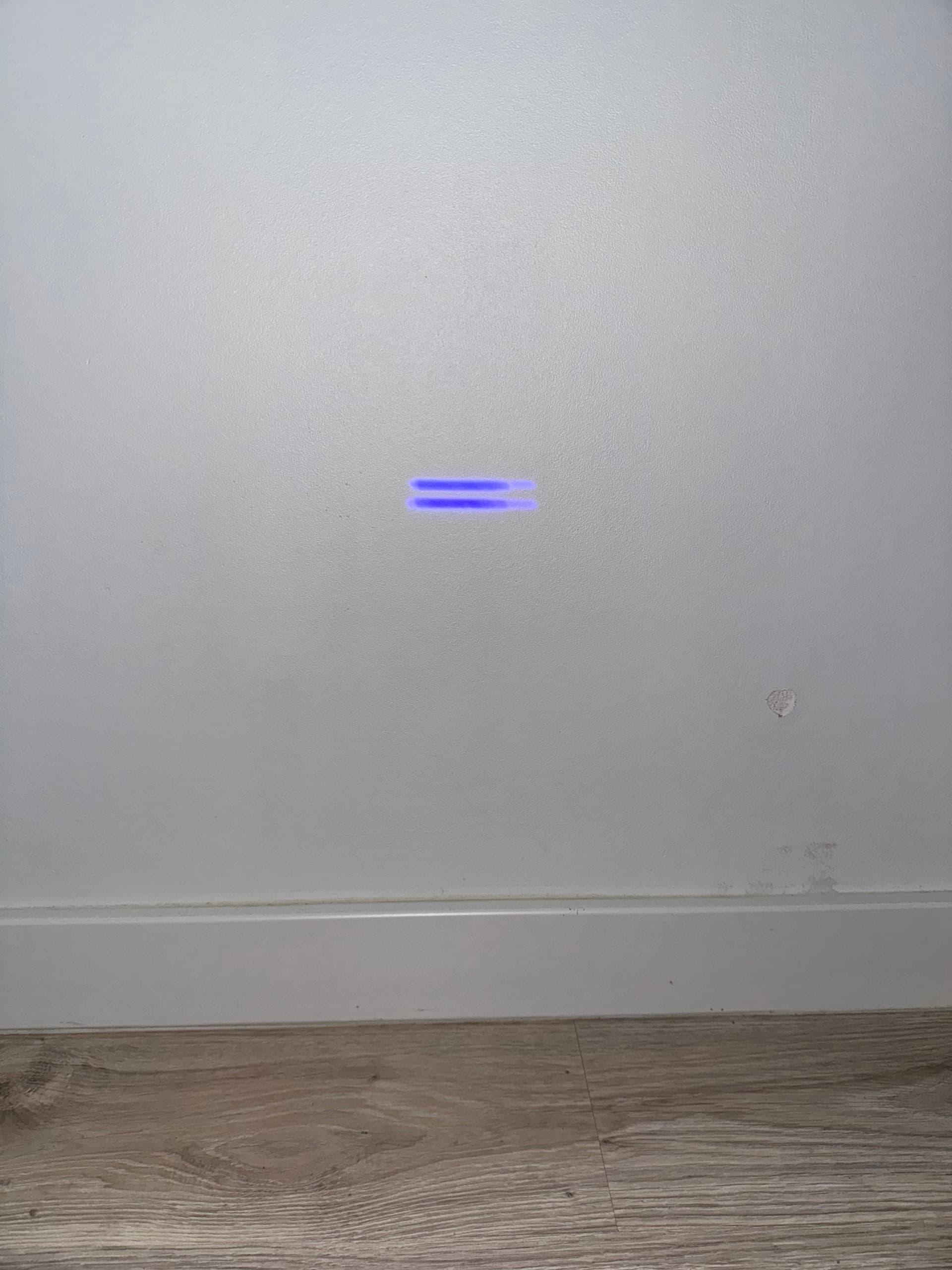
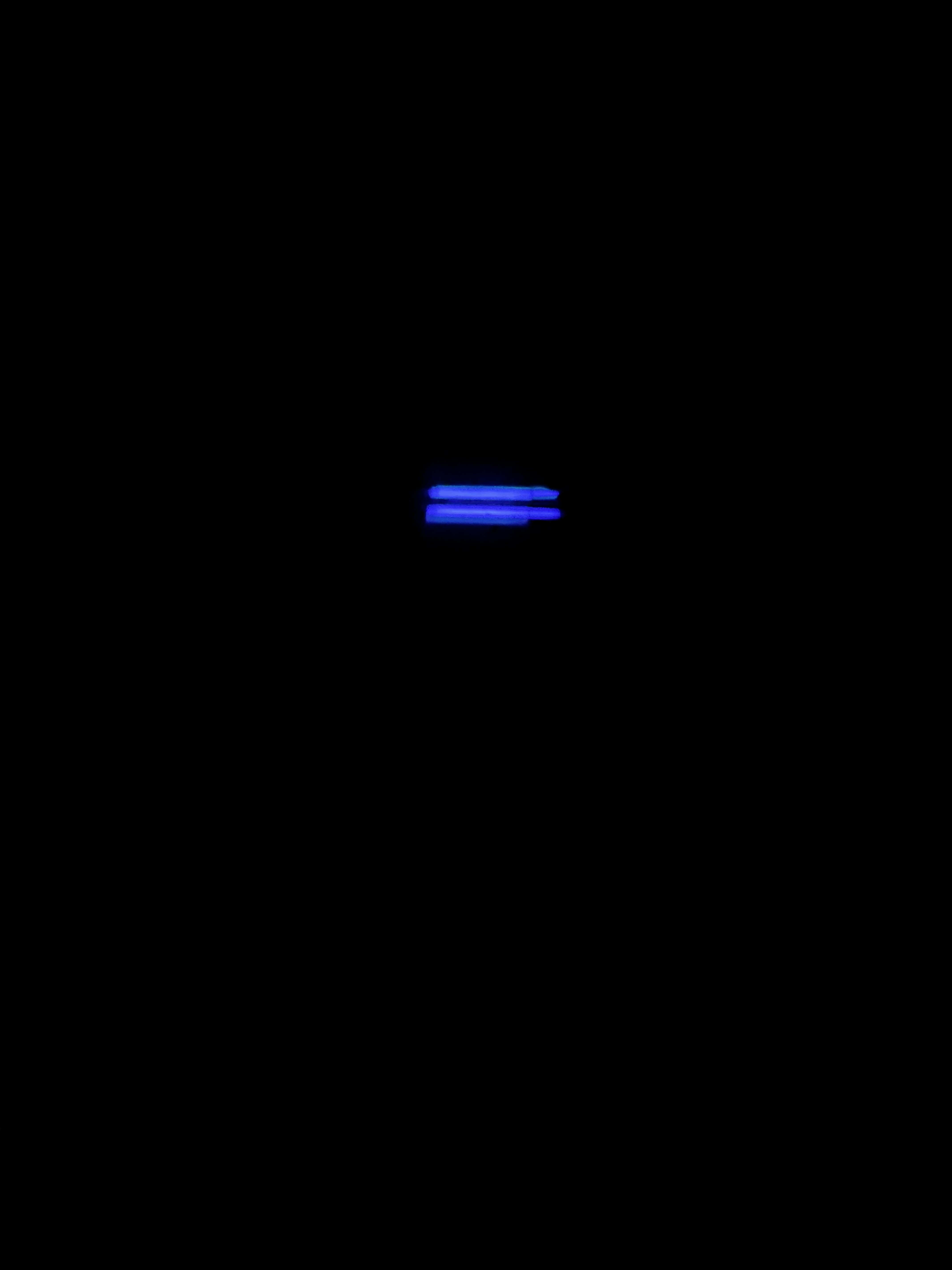
I’m not sure if this is exactly what you meant. I’m sending pictures of the test. Sorry for the delay, but work kept me busy. Thank you very much for your willingness to help with my issue.


If you take a look at the L vs R you notice there is a interesting change on the Y axis,
Makes me think the Left belt is much looser than the Right,
Also that the Y axis is not square with the frame.
If this is the machine:
Then, yes, that picture certainly suggests something is wrong: those long stripes cannot focus down to a square-ish spot.
I could be convinced there are four diodes contributing to those stripes:
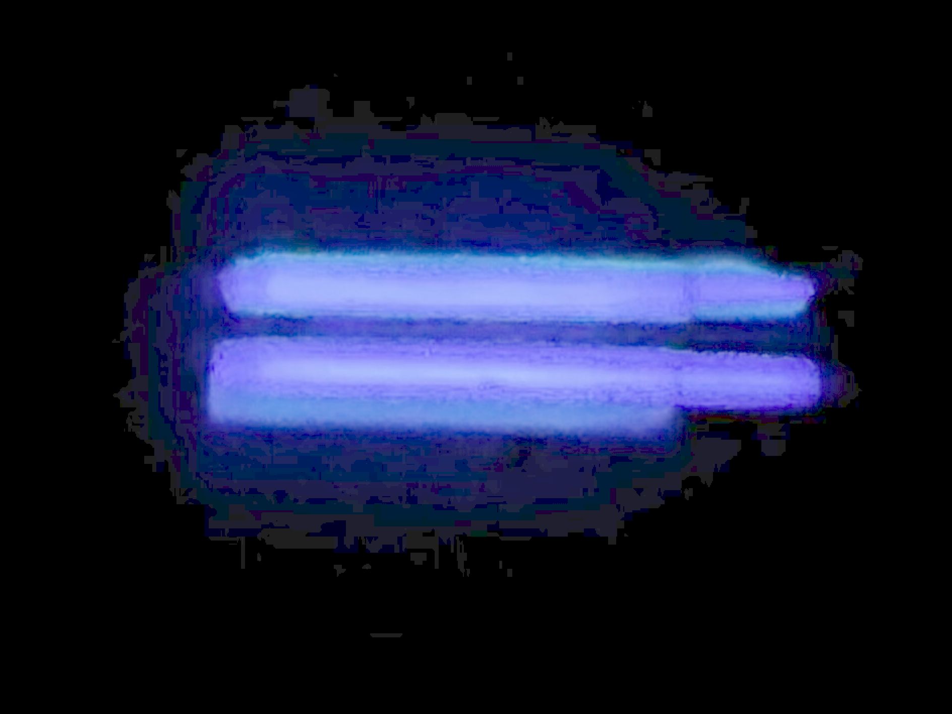
Two shorter bars with kinda-sorta sharp corners on the left, two longer bars smeared out to the right?
But I’d think two additional stripes, above or below what you see there, would make it more square-ish; those would come from a pair of laser diodes that are dead in your machine.
Maybe the beam combiner optics has shifted to overlay the two pairs of beams?
@gilaraujo: Is that what a four-diode spot should look like?
Seems like a double stack
2+2 yes that don’t seem abnormal to me
On the 40W ones you will have this x4
4 groups of double stacks
The specs say “its focus size (0.1x0.1mm actual focus)”, but the spot definitely looks rectangular out there on the wall …
I tightened the belt on the left side but the pattern comes out unchanged. The worst circle comes out where the laser is based (BL), and even though I did as you advised I unscrewed the screws from one of the gears and tightened the x-axle to the frame, when I let go of the X after that there is still a gap in the FR and BL. I also tried to disconnect the laser and keep the X axle tightened to the frame and then while holding it turn on the laser ( ON YOUTUBE someone had a problem with a crooked frame in this Neje laser and it helped him) unfortunately with me zero result. Is there any other good way how to straighten it ? One more thing, once I was able to cut an ideal pattern in FL after I gave the x-axis to the frame and then I turned on the laser, but when it finished cutting the pattern, the x was jammed in FL.