Is there a relationship between wattage capacity and kerf?
Situation: I currently have a 5W Sculpfun, and I’m considering a purchase of a 10W or 20W diode (possibly a Roly LaserMatic; would love feedback on this unit as well, if anyone has one). My 5W unit has been well-tuned and some parts upgraded, so it’s quite good at what it does, especially photos. Very fine pitch.
One application I’m using this for requires a very tight kerf, but I need more speed (don’t we all?), so I’m wondering if, let’s say I get a 20W, if that will likely expand my kerf. Related; is it wattage used or wattage capacity that matters? i.e. If you have a 20W laser, but run it at 5W, will that alter the kerf?
I expect that some of this depends on the specific laser module and/or the brand, but I’m looking to understand the general physics. We can talk about kerf for different brand lasers as well, but I suspect a lot of the diode lasers modules themselves are very similar.
The kerf is determined by the size and shape of the beam at focus. That aspect should be independent of power, but with a catch. Higher power with the same beam size can burn a wider swatch due to the extra heat. If you speed up the travel, you reduce this overburn effect. I found the Roly Lasermatic10 advertises an .08mm x.08mm beam. The Genmitsu Jinsoku LC-40 (10w) advertises a .08mm x.06mm dot (not said which axis was .06mm), so the kerf is likely to be different between the X and Y axis. I expect a round dot is better than an oval one.
A 5.5w laser uses about 40 watts of power. Manufacturers play games with the advertising, so read the info carefully. Laser output power is what I focus on. Also remember 5.5w is about the most you can get out of a single diode. Multiples of 5 are obtained using more diodes, which all have to be focused to the same exact point. The more complicated the machinery, the easier it is to gum up the works.
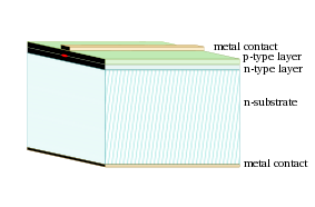
You are correct, the substrate in the diode is rectangular. and 8x8 cross corners, at 45 degrees, is 11.3. There is no fix the line (kerf) getting fat at those areas. It is a diode manufacturing issue. I need more coffee!
I am guessing the Roly diodes are rotated 90 degrees apart, giving the 08x08 pattern (x8y6 and x6y8). I wonder how a cross type beam would impact the circle…
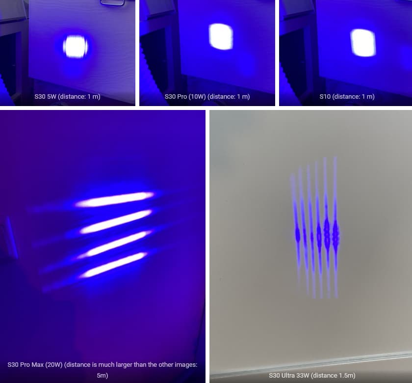
I think the others already mentioned all technical aspects. I can help out with some pictures
As a rule of thumb: the more power, the wider the beam. Because more power is only achieved by combining more diodes and align their beams. Since it is impossible to have those beam absolutely exact on the same spot, the beam widens.
If you use the same module, the percentage of power does not change the beam size (but maybe the area that gets burned, depending on material, as Mike said).
The advertised beam shapes are usually not true in reality, but over all, Sculpfun modules come quite close to it (except for the higher wattage modules, I measured nearly twice the size of the advertised spot size).
Though the beam size will differ, this is usually no problem with your project because you would need to determine the spot size ones and change your kerf offset accordingly. Then it shouldn’t matter, how big the spot is.
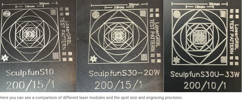
Here are some examples of beams and spot sizes, which you can find in my wiki at higher resolutions:
Nice Wiki page! I really liked the image showing cutting with 8 passes is faster than 1 pass. That goes to show what makes sense is not necessarily how it is.
So it seems to me that the biggest factor in this is probably the diode alignment/registration in each individual laser unit, which is going to come down to manufacturing quality control, and from a buyer’s perspective, luck. It also seems to me that better alignment would not only provide finer kerf, but probably better power transfer, but that’s just speculation.
Unfortunately, this does not bode well for what I’m doing, which is indeed dependent on the actual kerf width - the size of the spot does matter. Pieces join together. Of course I could cut every single piece separately from different places on the material, but that would be really messed up compared to the way it’s working now.
Sadly, or happily, depending on perspective, I happen to have a really well-tuned S9, which measured even better than spec, closer to .06mm. Which means if I move to something in the 10-20W range to get a speed boost, it may not work very well compared to what I’ve been using.
This was not the news I was hoping for, but it all makes sense, and I’m thankful for the replies. I may have to just give it a try to know how well it works in practice. It’s possible that the differences won’t be huge (?), but also seems like some luck involved.
Anyone have any practical experience with multiple lasers to know how this is likely to play out in actual real-world kerf comparisons between 5W and 10-20W? Or where I might find that info?
Yes, the Sculpfun modules are among the top of all diode laser modules regarding the spot size. The S9 is best in class of 5W modules.
In my experience, the S10 / S30 Pro modules come close to this, though not exactly. But it might be worth a try. If you have a section of a project, I could cut it using mine and have a look how they fit. In my opinion, those two modules have the best compromise of speed and precision on the market.
Anything above 10W will increase the spot size drastically compared to the 5 and 10W modules. I think this is common over all brands because it’s a physical effect. But I can’t tell for other brands, since I don’t have such modules for testing.
Thought experiment, kind of like Einstein, I got to wondering what would happen if I rotated the .08 x .06 rectangle along an arc of 90 degrees. This was to visualize what Jack’s hypotenuse rule would do to the line. Then I wondered if there would be a visible difference in line widths for .08mm and .06mm. The internet says the difference between the two was .0008 inches. I would consider this a non-issue and focus (pun intended) on the smallest dot possible.
Part of the difference comes from having the amount of energy applied to the material depend on the direction of travel.
With the spot aligned to put the longest side parallel to the X axis, each point of the material gets ⅓ more energy when the laser head moves along X than along Y. Moving along Y, the same point gets ¾ of the energy as along X.
So the direction matters:
With the speed & power set to the middle of “what works”, the differences won’t matter.
If it just barely cuts along X, it’ll fail along Y
Doesn’t that imply you should adjust for middle of the road? No need to bring in extremes to the game. Sort of good in X and not too bad in Y? I assume that is what you mean by “what works”. They could actually mfg a round diode laser chip, but not happening because not enuff money in the market for it. Two diodes set at right angles is about as good as we can get.
Thank you Melvin, this is exactly the kind of practical, real-world, info I was hoping for.
I am getting a much better idea of how this stuff works and it’s making more sense now. Aligning 2 lasers, especially if they’re slightly asymmetric and you can offset by 90 degrees, does seem a lot more reasonable than aligning 4 or 8 of them and hoping that not a single one of them is just a little off. We’re clearly still in the early stages of laser development.
Thanks for the offer of testing, that’s really generous. But it’s more of a whole class of cutting and fitting than a single fit (think mosaic), and I think right now I’m leaning toward getting the Roly 10W, which might be a different laser module. But at least I can be confident that it’s just 2x 5W inside, so at least fairly similar. If the kerf is at least fairly close to what I’m getting now, all the additional features (including a hood that will allow me to cut indoors) and a roughly 2x speed increase, will make it worthwhile. My Sculpfun will still be the way to go for photo engraving.
Assuming my current kerf is in the .06-.08 range, I don’t think it will be a problem if a faster machine ends up being something around .1, but I’ve read some people talking about the more powerful lasers being a lot wider than that, which was giving me some pause about waiting for the 20W version. I think I’m inclined now to just go ahead and get the 10W.
Generally visible light lasers are not very usable for metal work.
You can coat metal with something and cause it to bind with a small laser, maybe take off anodizing. But I doubt you’ll be able to engrave anything metal with the S10…
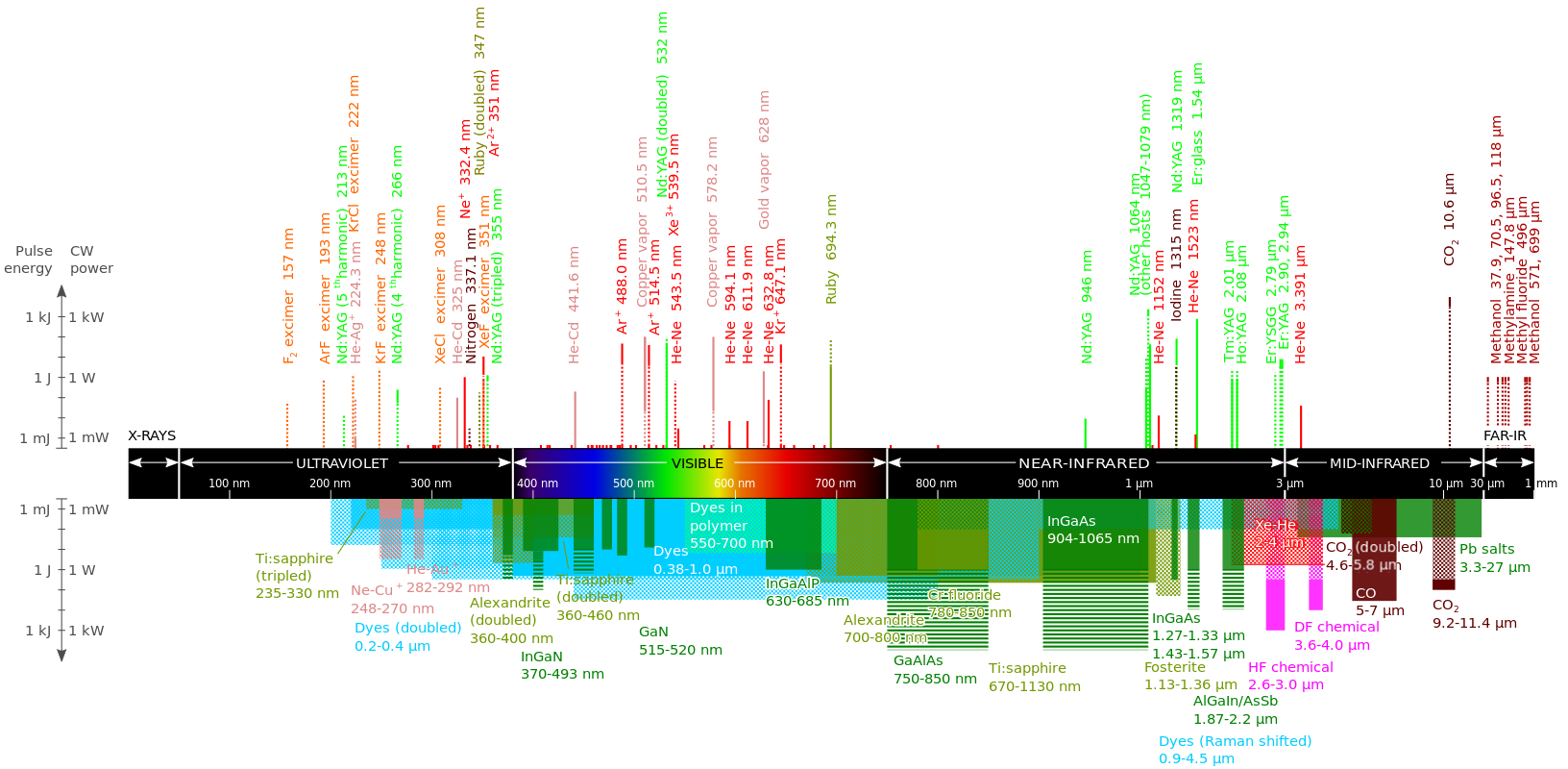
The fiber frequency is 1064nm in the IR spectrum and the visible light from the s10 is 455nm, same as your current laser…
Laser wavelength : 455±5nm
You can find 1064nm led type lasers, but they are not fiber and not low cost either.
I know the advertisement states 304 type stainless, but I’m suspicious it’s not engraving it. Most metals reflect over 90% of the beam and/or have good heat sinking, removing the lasers heat quickly. These attributes make working with metal tough.
My fiber is a 60W machine, the pulse output of it are in the 18kW power range… it’s a pulsed laser not cw or continuous wave like most lasers out there…
There are co2 machines that cut metal, but they are > 2kW in power. I’ve heard of smaller machines in the 300W range cutting metals, but all of these are outside of the normal hobby lasers.
I have a 40W co2 and I can only mark on metals with a coating. I managed to mark a stainless steel tag, rather poorly, and it cost me a lens…
There are some UV heads that could mount on your type of machine that will work on metals along with some IR heads…
Most people cough up the money and purchase a fiber… you have a lot more control, but you pay for it…