I agree.
Like, the car engine won’t start. There’s fuel, there’s a spark at the spark plug, the injectors are working, there’s fuel pressure at the injector nozzles, there’s a charged battery, the starter motor turns fine, the engine also turns fine but it won’t start.
Clue: if you put diesel instead of gasoline, will the car start?
As time goes by, more and more keep popping up…
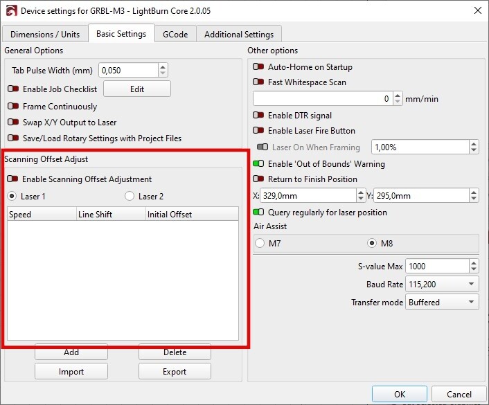
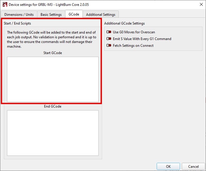
Although I don’t use any of this, I believe it might have some influence if:
Are there any definitions entered in these fields?
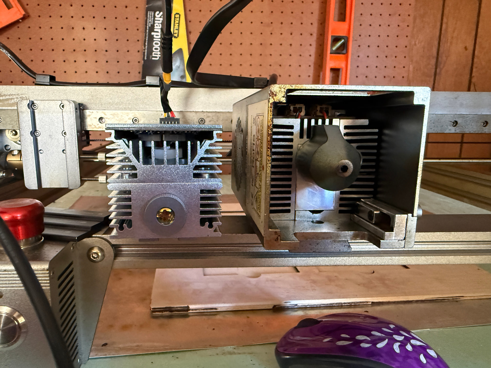
I used an aluminium card to do both on the “test” you suggested. The laser is in a different place on both modules as seen in the image attached. I also took a video at the request of Laser Tree that I will try to post as well
If you don’t know or aren’t sure, you say you don’t know. By stating “no,” it’s assumed that there is effectively no information there.
This means that there are no G-code entries to be added to commands through these definitions. I’ve never used them either, but I understand they are for making specific adjustments for a machine.
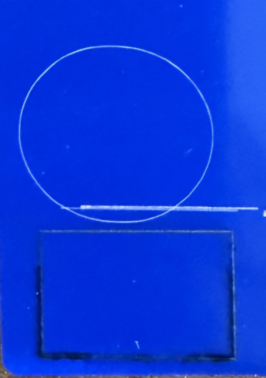
Which laser drew the circle and which drew the square?
At the beginning you mentioned that the deviation was to one side or the other.
In the image I see one drawing on top and another below. Was it exactly how it was engraved or is the image you posted rotated?
Sorry if I bother you with so many questions, but when I don’t know something, I try to clarify.
There are two separate and different laser modules in play.
The xTool has a sort-of GCode interpreter. It requites a special .lbdev file to operate in the usual sense. The Falcon is pretty much a generic GCode machine.
The Home position will not move because it is fixed by the limit switches. So there is an offset between the diode and I.R. 0,0 point. This means one module has to get an offset compared to the other. Did a little research and found an offset that works within, or on top of, the standard G54 (and G10 L1) default setting.
We can set up a G52 Macro for the second module. If that does not work, then G10 L2 will take care of it.
No worry, we will help and explain everything. What we need to know is how much X & Y it is.
The G52 G-code command is used to create a temporary, local coordinate system (LCS) offset on top of your active Work Coordinate System (like G54 through G59). Think of it as “shifting zero” to a new temporary position without modifying or deleting your original part zero.
I guess I am confused. My problem is not with my Diode, but the IR. It is the shift to the right by 1.5 inches that is the problem. What I have started doing, it letting the machine frame with the IR, and I line my project 1.5 inches to the right by moving the materials over.
I don’t understand what good a macro would be. I would still need to frame my project, so will the macro, when implemented, take care of that shift right?
I found today, that now, if I use Start Here or User Origin, I get an error of things would be out of bounds, and it will not continue.
Thanks for all your hard work.
I am just shaking my head in total confusion as to what all is going on with the IR module. The diode is fine. I could not post the video that shows the shift from the frame to the actual start because that extension is not permitted.
They are both on top of each other made to be layers, not the circle above the square but basically the circle inside the square. The circle was the IR, and the square was the diode. Oddly, the engraving of the IR did not move to the right on this particular job.
You are not confused. The I.R. is the addon, so it is the culprit.
Two very important questions:
Are both of those modules sitting on the side that mounts to the Xaxis trolley?
Is the top or bottom of the circle-square the side facing the front of the machine closest to the Home position)?
Click on the “I.R. Module” macro button and it will offset the 0,0 to compensate for the different size of the I.R. module.
Click on the “Diode Module” button and it will reset everything back to normal for the diode module.
Nothing else will be needed to do, to switch back and forth between the modules. I use Macro button to change settings when I switch to my rotary and back. Works like a charm. Of course, we must figure out what is needed for the switch. But once it is done, it is done.
Are you learning more about your machine than you wanted to know?
We did not learn this until posting #13, so please be patient with us. I think we are really close to a solution to your issue where the I.R. does not burn where it should.
We will be happy to explain whatever you are curious about. Just give us time to figure it out.