I had something similar when I was starting out. I had added a laser cross-hair that mounted to the lower left of the laser head of my Ray5. When I went back to absolute coordinates a few days later, everything framed great, but burned to about 1.5 in to hte right. Someone asked me if I had that type of add on and did I have my ‘enable pointer offset’ turned on under the Laser Tools/Dimensions/Units. It was! I turned that off and everything started working!! Hope this helps with your problem.
Mark B.
In the video the led cross-hair isn’t framing the width of the cards.
The modules were sitting on the mount side, yes.The square is closest to home and was done by the diode. The circle was supposed to be inside the square, and was done by the IR. The aluminium card was not moved. The card is long side left to right.
Going to show my ignorance. I don’t know where the macro button for the IR module is and not aware of where the button is on the diode. I am totally sorry. I know there is a macro tab, but there is nothing in that window.
Would need to see the file but it appears it’s framing the project. And to me it looks like it is lasering in the middle of the template.
It does not just happen on one file. It does it on any that I place for a project.
I don’t use the crosshairs…I use the beam
That is correct, we are not there yet. Do not worry about that for now. I just mentioned it so you will know there is a light at the end of the tunnel. Or in other words, I think we see what is happening and we have a solution.
We have no information on the size or coordinates, so I have prepared a test file to help with that.
- Load the file, mount the I.R module, and home the machine.
- Burn a spot on your test material, preferably a light colored wood scrap. You can use the Fire button in the Move window for this.
- Without moving the test target, install the diode module and re-Home the machine.
- With the diode, burn the square. You should now have a square with a dot somewhere close by.
- Take a picture of the test burn and add it to your Reply
By knowing the size and location of the square, I should be able to get pretty close to the offset needed for running the I.R. module.
Diode-IR Position Check.lbrn2 (20.7 KB)
Do I do the burn from the home position? If not, where do you suggest?
I will do the test tomorrow. I have an appointment to get back injections. My back is a mess and we are trying anything in order to avoid a multi-level fusion. I have downloaded the file you attached.
Thanks again for all your assistance.
DUH The file has the positions already. Face smack 
Take care of you first! This can wait.
I went the civilian Dr. route, and got little relief. Being a Veteran, I chatted with my VA Dr. and now I am getting more advanced service beyond PT and Tylenol. I know this might sound patronizing, but I feel your pain.
While Mike tries to address how to solve the problem, I’m trying to figure out what’s causing it.
Apparently, there’s something more than just the size difference between modules influencing it.
Now, please clarify my curiosity.
What are the dimensions of the modules? Width x length (I don’t need the height)?
How does the machine know which module is mounted?
Or does it not know, and you’re the one who has to pay attention to which module is mounted?
Considering this detail, you may be facing a “problem” in the file.
Check what happens with different existing files (jobs).
Does the deviation remain horizontal?
Check what happens with new files (jobs).
Does the deviation become vertical?
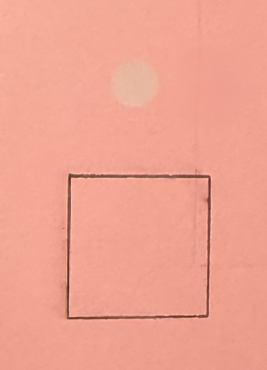
I attempted to do your file with wood. The IR module will not burn wood no matter how I tried to get it to work. What I wound up doing was using a light colored business card since both modules will show up on the aluminiumI resized the square to a half inch and place a circle in the middle for the laser. I had the diode line the square and the IR to fill the circle.
IMG_3503|360x500
I was hurt on the job in 1999 and had 3 surgeries on L5-S1 with the last being fusion. I then had L5-L4 done in 2016 and then L4-3 L3-2 done in 2022. Now, I have more garbage going on including “really large bone spurs” and quite a bit of compression. This was my 2nd set of injections, with the 1st being a test (6 injection sites) and today, 6 again but steroids today. We shall see what will come of this. The “crap” shooting down my leg has not been addressed. These injections are focusing on the back alone, not the nerves that are impinged in a couple of places. I have delayed this since the start of the new year, because I wanted to enjoy my already planned vacation to Grand Teton and Yellowstone. I am 73 and can’t even walk around my neighborhood because my back makes my legs very weak. The dogs hate that they don’t get to go for a walk.
I hope the injections get you through that, t least!
I thought I had it computed until I read this. I need your .lbrn2 file so I can get the actual square and circle locations from that. You say a circle for the I.R., but all I see is a big dot.
I went out there in June. It was amazing. Grand Teton is magical and Yellowstone was very special…a scientific wonder. I was there the 5th-11th of June. So special and so different in that they are only 70 miles apart.
BTW, thank you for your service. My father (enlisted during WW2/army air corps and enlisted during Korea/ Air Force- he had become an MD) and one brother (Army) served and my X (Marines) served both in Vietnam.
Cancel this. I think I have it.
- I.R module mounted, Home the machine.
- In the Console window, enter G28 X-.511 Y-14.617
- Run a test with the I.R.
- Let me know if it burns where it is supposed to.
Then we go from there.
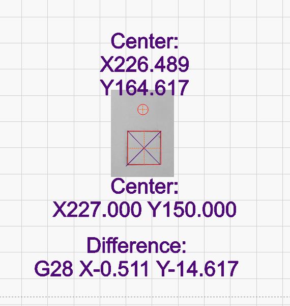
Edit: I may have the signs backwards. You said earlier the I.R. was giving the out of bounds message?
That was only when using either User Origin or Start Here. Otherwise it work…well sort of.