Burn a square with the I.R. Enter G28 X0 Y0 in the Console. Then burn the same square with the diode. They should be pretty much on top of each other
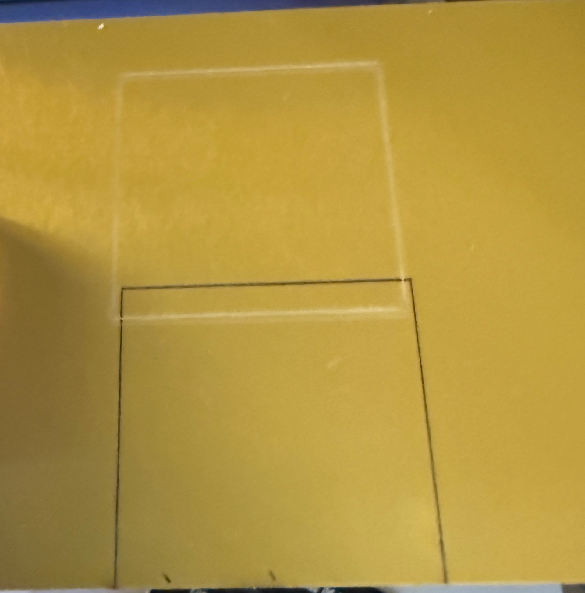
Did not expect that much offset. 2" or 1/2" squares?
Please work in mm only so we do not get conversion issues.
Can you do the same test, but with no offset for the I.R.?
G28 X0 Y0 for both (you only have to enter it once).
And let us know what size square you are using.
1 inch square and I did it twice. Once with original line you posted and then the 2nd line. The images were the same.
I do not have offset turned on in the basic tab. I will attach the file in a minute, I think it is still on the screen, otherwise, it is gone…
MIKE H.lbrn2 (3.4 KB)
The outside rectangle was only for placement purposes, needless to say.
Please confirm this one was produced with no G28 offset (G28 X0 Y0).
With the perspective angle, exact is not possible. But try this:
- I.R module mounted, Home the machine.
- In the Console window, enter G28 X-.530 Y-19.300
- Burn your square with the I.R. using the MIKE H file you sent me.
- Mount the Diode module and Home the machine.
- In the Console window, enter G28 X0 Y0
- Capture an image of the result. Straight down if possible. The squares should look square.
- Upload your image.
I need to confirm the G28 is actually working in your controller.
Here is a new file to try.
- Home the machine.
- Enter G28 X0 Y0 to cancel any offset.
- Run the blue square with the diode.
- Run the red square with the I.R.
- They should be on top of each other. Maybe!

No file…but, if I enter the command into the console, does that stay, I notice that there is not $ in front, so I am going to assume, no.
I did the Please confirm this one was produced with no G28 offset (G28 X0 Y0).
With the perspective angle, exact is not possible. But try this:
- I.R module mounted, Home the machine.
- In the Console window, enter G28 X-.530 Y-19.300
- Burn your square with the I.R. using the MIKE H file you sent me.
- Mount the Diode module and Home the machine.
- In the Console window, enter G28 X0 Y0
- Capture an image of the result. Straight down if possible. The squares should look square.
- Upload your image.
That you see in the image I posted, exactly as as the you requested minus the Mike H file. The 2nd line I typed for that image was G28 X-.511 Y-14.617
I will have to convert to mm because I do imperial and while being a retired teacher. I have never used the metric system.
MIKE H - New Test.lbrn2 (22.3 KB)
Sorry, I got side tracked!
It is “modal” which means it stays in the controller while the power is on until you change it.
Being a temporary setting, it likely ceases when you reboot the controller, but I am not sure.
That $ is a controller command. This tells the controller how to operate.
That G is a program command It tells the controller what to do while it is operating.