Is that because LightBurn caps the value at 20%? You could potentially create a macro to create your own fire button although it wouldn’t work for framing.
F51 is 20% power when $30=255.
M3 F51 G1
To disable
M5
Arduino compatible boards all use 255 as value for $30. Discussed here with @JohnJohn:
In either case as you say it’s important that the value agrees with S Value Max.
Here’s the relevant portion in GRBL cpu_map.h file that shows this:
    // Variable spindle configuration below. Do not change unless you know what you are doing.
    // NOTE: Only used when variable spindle is enabled.
    #define SPINDLE_PWM_MAX_VALUE     255 // Don't change. 328p fast PWM mode fixes top value as 255.
    #ifndef SPINDLE_PWM_MIN_VALUE
      #define SPINDLE_PWM_MIN_VALUE   1   // Must be greater than zero.
    #endif
    #define SPINDLE_PWM_OFF_VALUE     0
    #define SPINDLE_PWM_RANGE         (SPINDLE_PWM_MAX_VALUE-SPINDLE_PWM_MIN_VALUE)
    #define SPINDLE_TCCRA_REGISTER    TCCR2A
    #define SPINDLE_TCCRB_REGISTER    TCCR2B
    #define SPINDLE_OCR_REGISTER      OCR2A
    #define SPINDLE_COMB_BIT          COM2A1
Even the manual for @capt835’s laser refers to S100 and S200 values when assuming S1000 max. But from what I can tell this is for different controllers than what @capt835 has. That would put it in the 10-20% power category. This seems extremely high but hard to say without having familiarity with this specific module.
Yes, I’m using the included power adapter and plugging that into the control adapter.
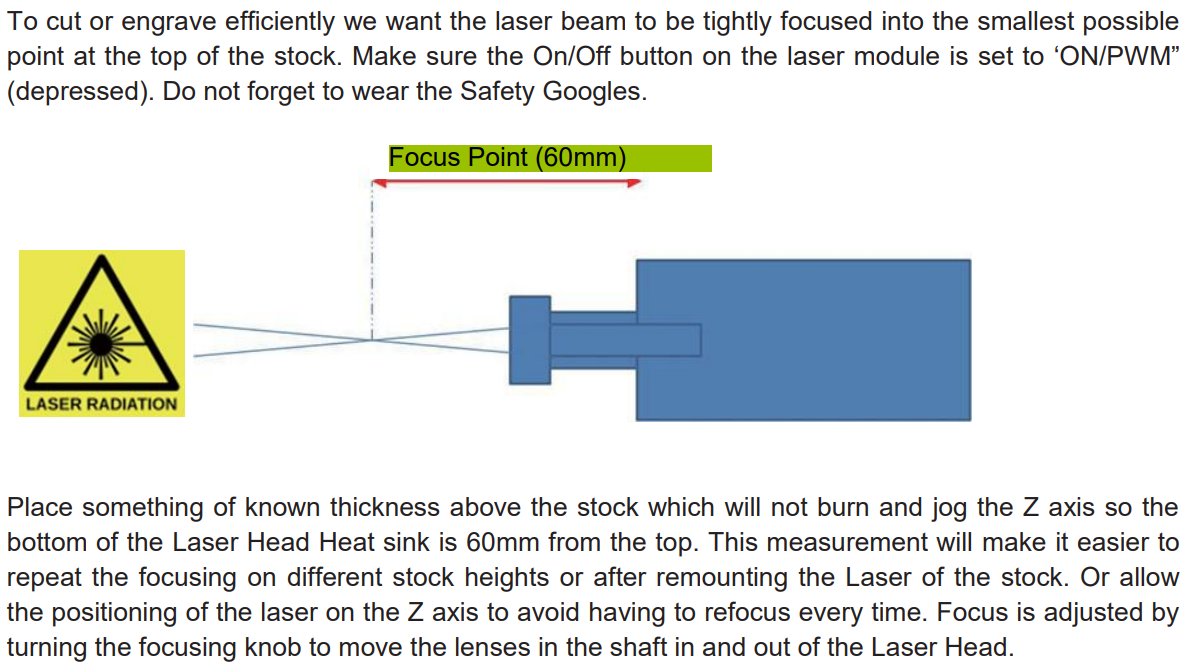
I tried both focusing methods at 60 mm and 50 mm. They both work equally.
Can you tell me where you saw the mention of power levels between 10 and 20 % for focusing.
I first checked the power outfeed to the laser. This is where things got weird:
I set up a straight line about 5 inches long on the X axis and had it double back. I set the F/P at 400/50
Power Adapter unplugged - 0 output voltage
Power Adapter plugged in - 0 output voltage
Start the run - 12 VDC
End the run - 12 VDC
Power Adapter unplugged - 0.5 VDC
I repeated that a few times and got the same results. I even changed the F/P settings and while it was running the line, I increased the power by 10% in 5 steps and down 10% in 5 steps. So 50% up and 50% down. There was no change in the 12 VDC.
So I checked the input voltage going from the GRBL control card to the laser control adapter. There is where I got the 0 to 5 VDC and it varied as I bumped it in 10% steps up and down. Which functioned normally I’m supposing. I don’t get the 12 VDC to the laser.
I did write SainSmart and they said this setup I have should be set at S Value Max 1000 and $30=1000. No change.
After I checked the voltages, I ran some simple tests and again 10 to 30% I have laser on but no burn even at a slow feed rate of about 100 mm/min. I do get a light burn at 37.5% power. So that tells me somehow the control adapter is modulating the power to some extent.
I inferred it from the examples they gave. They had a Mach3 example where they set power to S200 I think with an assumed max of S1000. There was another example in GRBL with S100 with assumed max of S1000 for the Prover. I assume that’s for a different controller than yours but the percentage should hold true for your laser since it’s the laser module that’s being driven at those duty ratios.
I just rechecked the control board and laser and I think I misunderstood the relationship between the board and laser. I think the control board contains all the logic and power management and the laser module is really not a module at all, and just the diode, heatsink, and fan. Other laser modules I’m familiar with directly take PWM/TTL between 0-5V. In those setups control adapters are really there to offer different methods of providing that signal and power.
However I realized that your laser module only takes 2 wires. Which means it’s receiving the 12V power line voltage. That means that the control board is processing the PWM and adapting it for the laser. In that case I would have assumed that it would simply be converting the input 5V TTL/PWM to 12V TTL/PWM but your testing indicates that it’s getting a full 12V the whole time. I would have expected it to be 6 V (50% of 12 V).
I’m curious how laser power is being modulated then. I’m guessing that it’s current controlled but I’m not sure. Are you able to test the amperage at various power levels? This may be a little tricky as you may need to get some extra leads and assuming you’d need to have the laser firing as this happens.
Did you check laser side voltage at <30% power setting?
Well I guess that’s settled. I don’t know why the controller shipped at 255 and don’t know why they have deviated from default for Atmega328.
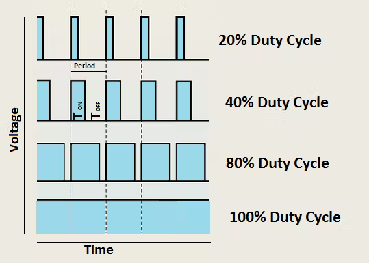
I searched on “What is PWM in Arduino”. It appears the frequency, not the cycles, of the applied 12VDC is adjusted based on the 0 to 5 vdc signal from the GRBL Control board. Here is an image they show.
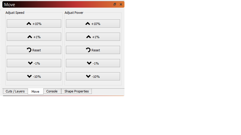
So I’m guessing I would need a scope to look at that. However, I was able to see the laser intensity change by having the laser run a square at 50 mm/min and using the “Move” window to increase the power in 10% steps.
So at this point, I’m guessing my GAP problem was resolved by adjusting the $120 and $121 Acceleration speeds so the laser fires faster when it changes direction. Now I just guess I have to tweak the feeds and speeds so as to get the graduations to show more of a change in the Power Speed and Grayscale tests. Thanks for all your input and if you have any other comments to make regarding this, I’m all ears or eyes in the case of reading these threads. jkwilborn Thank you also Jack. DougL Thank you Doug. Also, thank you all if I missed anyone.
To see the actual PWM yes. However, a meter will show an “averaged-out” voltage in proportion to the duty cycle. So 50% duty cycle on a 0-5V TTL signal will show as 2.5V on a meter.
Keep in mind this is all going to be on the controller side of the control board. Apparently the laser side of the control board isn’t PWM.
It was likely addressed by going faster but I would characterize the mechanism a little differently. What caused the gaps is that the laser intensity is reduced to prevent burning as during the deceleration caused by the direction change. However, because of the “deadband” or drop-off point of your laser it reduced intensity to the point that it wasn’t strong enough to burn at all. Going faster overall probably kept the speed at a high enough level as to not call on a power level where the cutoff occurs.
The two wire lasers, like came with my cnc3018, just switches the power on and off to the laser. There were no electronics on my supplied 500mw module. It was a heat sink with the led laser on it.
Is the ‘time’ scale for your graphic in minutes, seconds, days or years?
The earth spins under the sun which produces a pwm sun period that varies from winter to summer. It just has a slower rise/fall time and a 24 hour period. ‘On’ more in the summer, than off… In the end it’s all time relative
My Ruida is 20kHz, which I can change via Lightburn. The Arduino, which is in my cnc3018 is about 1kHz and you have to recompile the firmware to change it. The step rate of the Arduino is up 255 steps from 0 as it’s only an 8 bit register…
As you acknowledge, you can see the ‘power control’ of a laser is on or off. We only see an ‘apparent’ power change because of the ‘average’ time the laser is on. Our only real control is speed…
How was power modulated on that unit? Also, did it take 12/24V from power supply voltage? I’m curious about @capt835’s laser as voltage showed steady 12V irrespective of power setting meaning it’s likely not PWM. This to me means there’s either no power modulation or it’s modulated some other way. Since we can clearly see that there is some level of power modulation it’s not the former. I assume current-controlled but not sure. I haven’t worked with a laser like this.
The machine needs it’s 12v for the motors to operate. The controller runs off the usb supply.
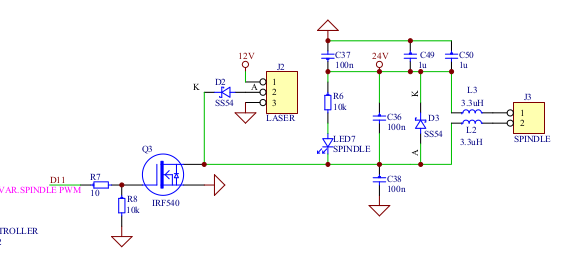
The connector used the 12v and the ‘pwm’ completes the ground through the IRF540 mosfet… it’s only 500mw laser.
The mosfet is good to 33A…with a proper heat sink.
Lasers are on or off. The pwm in this instance just turns the power on and off. Co2 turns the high voltage on and off controlled by the pwm. There is no 50% lase.
I blew the output of one channel in one of them and keep the board around to generate pwm when I need it. I plug it into the laser output.