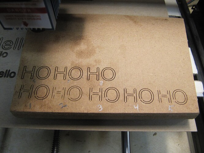
I recently changed to the GRBL V1.1f controller. I haven’t had much time to use it. I thought I followed the setup procedures correctly. I’ve tried making the min and max speed the same. I tried variable feeds and power settings but the gaps are still there. I made sure I set the $32=1, I set the S value max to 1000 and I tried to search on “Gaps” in the forum to see if anything came up but I came up blank. By the way I never experienced these gaps when I was running the 3018 MX3 board. I switched to the GRBL board because I was told it was more compatible with Lightburn. Thank you, Bob
Can you provide the following to help troubleshoot?
- Post a photo of what you’re seeing?
- Enter
$$into Console and copy-paste the output here - upload the .lbrn file that you’ve been using to test this
Thank you for your response.
Test HO For Gaps.lbrn2 (14.0 KB)
$$
$0=10
$1=25
$2=0
$3=2
$4=0
$5=0
$6=0
$10=0
$11=0.010
$12=0.002
$13=0
$20=0
$21=1
$22=1
$23=3
$24=25.000
$25=500.000
$26=250
$27=1.000
$30=255
$31=0
$32=1
$100=800.000
$101=800.000
$102=800.000
$110=2000.000
$111=2000.000
$112=600.000
$120=10.000
$121=10.000
$122=10.000
$130=500.000
$131=400.000
$132=100.000
ok
This is my first time replying to an inquiry. I’m not sure if I provided the information correctly that you requested.
Thank you,
Bob
Lightburn Common Grbl Setup instructions
Set the spindle max value ($30) to match LightBurn and Grbl’s default setting (1000)
This could cause the problem because you are not getting full pwm control.
![]()
Thanks Bob. You’re good with how you posted.
I’m a little puzzled by the photo. I would have never guessed this was how it was looking.
My first impression was that your belts were slipping but after looking at it more closely I’m not sure that’s the case.
Your test file only contained the letters “HO” so didn’t seem to match your burn. Even with that I think there are a few things to be learned from it.
- It looks like you may be significantly out of focus. How are you focusing the laser? I assume you have a Z-axis motor. Try to improve focus and rerun the test.
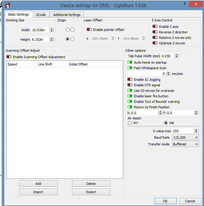
- Your GRBL configuration has homing enabled. Can you confirm you have homing switches on your machine?
- @jkwilborn may be onto something with the $30=255. However, instead of changing $30 to match 1000 it’s probably better to change the S Value Max in Device Settings to 255. I assume you got this board from the manufacturer of your laser or is this a DIY build? Typically 8-bit boards have values from 0-255 for this setting based on the data type used for this. Newer boards and versions of GRBL have changed this to 1000 which is why LightBurn now defaults to 1000 for this.
@jkwilborn Check out this dicussion with @JohnJohn for reference on this. My followup is directly following John’s post:
Isn’t that, they need to be the same?
![]()
Sorry, I picked the wrong photo. The HO looks exactly the same with the gaps. I was just trying some different shapes and sizes of the word “Hello”. I don’t have belts driving my Genmitsu 3018. It’s lead screws directly connected to the stepper motors. I’ll try refocusing the laser. I use a 50mm gage block. The laser, a 5.5W, has an adjustable focus but I feel more comfortable bringing it down to the gage block. I do have homing limit switches as well. Also, yes I purchased the GRBL control board from SainSmart. I did check with SainSmart and the board is an 8 bit board. I’m guessing this next question is, well you know what I mean, “dumb”. When codes are entered into the console, do I have to re-enter them any time I exit Lightburn? Also, I will make the change to the speed as you suggested. Thank you again for the help. Bob
That’s one requirement. But at least in the case of Arduino based controllers the value itself is determined by the data type so is supposed to be capped to 255. I won’t repeat the mundane details here since it’s in the other post but take a look if you’re curious.
Don’t think we’re there yet but there may be an issue with backlash based on the incomplete circles.
Gauge block is great. But you’ll need to make sure the focus is good at 50mm. After that you should be able to rely on the gauge block exclusively.
Any GRBL configuration changes are written to non-volatile memory and will be retained. Or at least they should. Some manufacturers prevent writing permanent changes.
And to clarify, this is not a GRBL Configuration change. This is a change in LightBurn to match GRBL. It needs to be done in Edit->Device Settings. And looks like you’ve already gathered but GRBL repurposes the spindle speed for laser power.
Oh and by the way… there are no stupid questions. Better to ask than to remain ignorant.
Hi, I didn’t want you to think I disappeared. I’m involved with a bathroom upgrade at the same time. I should be able to try out your suggestions later today or tomorrow. I will keep you posted. Thanks again, Bob
Good afternoon, The bathroom is complete. No leaks and a happy wife.
1st Test - I first focused the laser. It was out of focus and it seems to be burning nice and sharp but with feed/power at 500/50 Still Gaps
2nd Test - I then changed the S Value Max to 255. I ran a test “HO” letters at F/P 500/50. I noticed when I pressed the “FIRE” button with power at 7%, I could not see the light. I increased the power for the “FIRE” button to it’s maximum of 20% and I still couldn’t see the light with the glasses on. However, I did see a very faint dot without my glasses.
3rd Test - I change the F/P to 500/75. Still had gaps.
4th Test - I changed the F/P to 500/90. Still had gaps but larger.
5th Test - F/P 700/90. Still gaps and larger.
6th Test - F/P 300/90. Still gaps but the best yet, Gaps were very small.
7th Test - F/P 400/90. Still gaps bigger than 6th test results.
8th Test - F/P 400/100. About the same as the seventh test.
I checked the backlash on the lead screws. There is approximately 0.010" on the X Axis and 0.005" on the Y Axis.
This is the result, below, of the $$.
$$
$0=10
$1=25
$2=0
$3=2
$4=0
$5=0
$6=0
$10=0
$11=0.010
$12=0.002
$13=0
$20=0
$21=1
$22=1
$23=3
$24=25.000
$25=500.000
$26=250
$27=1.000
$30=255
$31=0
$32=1
$100=800.000
$101=800.000
$102=800.000
$110=2000.000
$111=2000.000
$112=600.000
$120=10.000
$121=10.000
$122=10.000
$130=500.000
$131=400.000
$132=100.000
ok
In regards to the backlash, when I was using the M3 control board, I never got any gaps. So I’m thinking the backlash would be negligible.
I ran those tests thinking if the feed rate was slower, it would have time to burn at the corners or ends of the circles. Then I remember something about increasing the feed to the power would be increased by the controller.
I’m lost.
Thanks for your help in advance,
Bob
You would have to check, but I believe Lightburn recommends $30 is 1000. There is a setting you have to match in Lightburn. Sorry don’t remember which, but the Lightburn common grbl setup explains it.
![]()
This is going to be the fundamental issue. It seems your unit is either very underpowered and/or is cutting off rapidly when the laser is slowing down for the corners. Power modulation is normal behavior for GRBL 1.1f and newer to avoid burning but somehow you’re getting a very sudden dropoff in power.
Have you run any test patterns to see if you’re getting power modulation? Might be worth trying this. Your test results seem to show very little variation in engraving darkness. I would have expected to see a bigger difference between 70% and 100% power.
This is a popular site to build a test pattern:
Lightburn PowerScale Generator - O2 Creative
For a sledgehammer workaround you can use “Constant Power Mode” in Cut settings. This will basically turn-off variable power and you won’t get the drop-offs.
Based on your latest results I don’t think backlash is related to what you’re seeing. At least it’s not the significant contributor.
Thanks, I’ll check that out as well.
I’ll try the test pattern and the sledgehammer workaround with the “Constant Power Mode” in the Cut settings.
Thanks again,
Bob
are you working in mm/min or mm/second? this threw me for longer than i’d like to admit.
I believe this is mm/min as the initial sample .lbrn file is in that range.
@capt835 forgot to mention before but your lines still look really thick for a line operation. I know you said you revisited focus but I have to think something is wrong. Those lines look like they’re over 1 mm in width. I’d expect them to be barely a sliver. It may be that you’re just overburning as well but somehow I don’t think so.
You may want to check your lens and make sure it’s not dirty. Clean it out with some IPA maybe.
Good afternoon, The bathroom is complete. No leaks and a happy wife.
1st Test - I first focused the laser. It was out of focus and it seems to be burning nice and sharp but with feed/power at 500/50 Still Gaps
2nd Test - I then changed the S Value Max to 255. I ran a test “HO” letters at F/P 500/50. I noticed when I pressed the “FIRE” button with power at 7%, I could not see the light. I increased the power for the “FIRE” button to it’s maximum of 20% and I still couldn’t see the light with the glasses on. However, I did see a very faint dot without my glasses.
3rd Test - I change the F/P to 500/75. Still had gaps.
4th Test - I changed the F/P to 500/90. Still had gaps but larger.
5th Test - F/P 700/90. Still gaps and larger.
6th Test - F/P 300/90. Still gaps but the best yet, Gaps were very small.
7th Test - F/P 400/90. Still gaps bigger than 6th test results.
8th Test - F/P 400/100. About the same as the seventh test.
I checked the backlash on the lead screws. There is approximately 0.010" on the X Axis and 0.005" on the Y Axis.
This is the result, below, of the $$.
$$
$0=10
$1=25
$2=0
$3=2
$4=0
$5=0
$6=0
$10=0
$11=0.010
$12=0.002
$13=0
$20=0
$21=1
$22=1
$23=3
$24=25.000
$25=500.000
$26=250
$27=1.000
$30=255
$31=0
$32=1
$100=800.000
$101=800.000
$102=800.000
$110=2000.000
$111=2000.000
$112=600.000
$120=10.000
$121=10.000
$122=10.000
$130=500.000
$131=400.000
$132=100.000
ok
In regards to the backlash, when I was using the M3 control board, I never got any gaps. So I’m thinking the backlash would be negligible.
I ran those tests thinking if the feed rate was slower, it would have time to burn at the corners or ends of the circles. Then I remember something about increasing the feed to the power would be increased by the controller.
I’m lost.
Thanks for your help in advance,
Bob
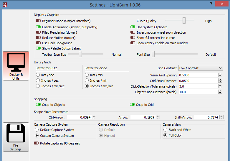
I believe I have the settings correct for mm/min. Is this the only place to make this setting (in the General Lightburn Settings)?
2 interesting things in Device Settings:
- You’ve enabled Fast Whitespace Scan but it’s set to 0 mm/min. Not even sure what that would do. This is basically the speed used for traversal moves.
- You’ve enabled Use G0 moves for overscan. Any reason for this?
Neither of these should affect your current problem but just a little unusual.


