Hi, I checked the line thickness. The lines are about .4mm thick. The overall letter H size is 10 mm wide and 12.5 mm high. I think maybe the macro lens through you off. I run a fan when burning and I probably don’t have more than an hour or two of use on the laser. I’m going to try the sledgehammer workaround with the “Constant Power Mode” today and hopefully get to the Lightburn PowerScale Generator from O2 Creative today.
That scale is larger than I anticipated but the line thickness still seems wide. .4mm is about the size of the kerf I would expect if you cut clean through. For a light line engraving I would expect something like half that.
When you do the PowerScale try with both Constant Power mode on and off.
300 inches/min is 7620 mm/min (90% power)
$110 & $111 are 2000mm/min (maximum)
Please confirm the units for your settings in your Cuts / layers window. ![]()
[quote=“JohnJohn, post:23, topic:60372”]
300 inches/min is 7620 mm/min (90% power)
$110 & $111 are 2000mm/min (maximum)
@JohnJohn - Please confirm the units for your settings in your Cuts / layers window.
[/quote] The reference to F/P 300/90 is mm/min. I checked the “Cuts / Layers” window and that’s what’s referenced there.
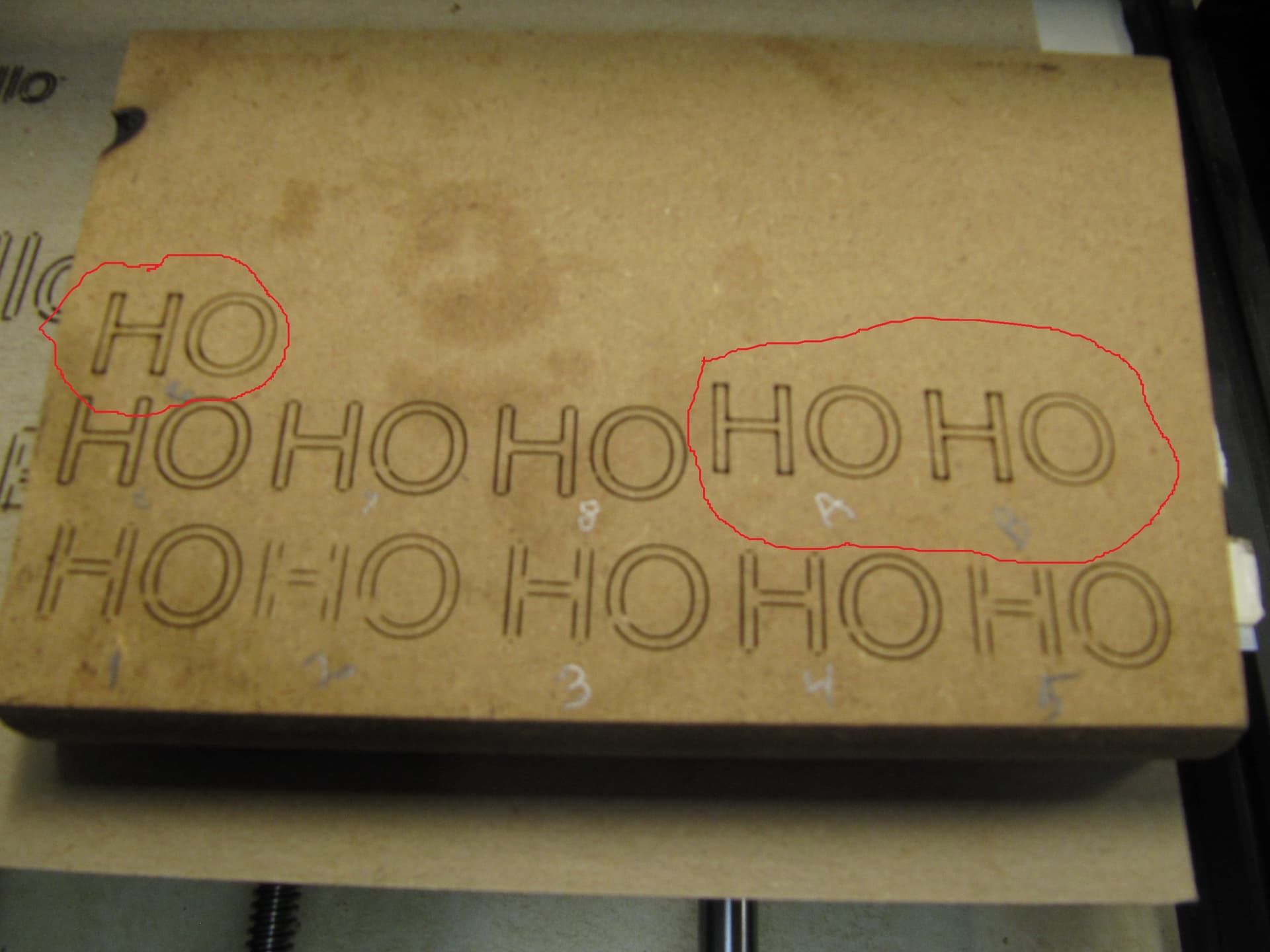
@ [berainlb] I did 3 tests with just trying to burn the letter “H” with the “Constant Power” set at A - F/P 400/50, B - 800/50 and C - 1400/50. There were no gaps but instead there were burned dots. I would expect to see that where the laser isn’t reducing power at the change of directions. One other thing I noticed is it didn’t seem evident the Feed rate increased when I ran at 400 mm/min as compared to 1400 mm/min. I will run the full test, as you suggested, tomorrow. I also read something regarding the $11 and $12 acceleration settings. Currently they are 0.010 and 0.002 respectively. You also mentioned my engraved line appears to be still too big at 0.4mm. I adjusted cleaned the lens and adjusted the focus to the smallest dot I could get. As I mentioned early on in the thread, after I set the S Max at 255, I can not see the laser dot when I press the “Fire” button unless I turn off all the lights in my shop and set the power to 20%. I then put the S Max back to 1000 and I can see the laser dot at 7% when the “Fire” button is pressed. Does that sound odd?
Your acceleration settings ($120 and $121) are extremely low, so as the laser is ramping up to speed in Variable Power mode, it starts with the beam off, and increases the power toward the requested value as the head gets to the requested speed.
If you increase the acceleration value (try 100, then 200, then 400, …) you’ll find those gaps become much shorter, possibly non existent. You might have to set these values back when using the spindle again, but you might be able to find a middle ground that works for both.
It’s hard to tell from the pictures, but it’s quite possible the laser is also not properly focused, which will make this problem worse - if you get a nice tiny beam spot, the energy is more likely to mark the material at lower power.
Actually these are not acceleration settings but rather for Junction Deviation and Arc Tolerance. Acceleration settings are $120 to $122. I agree with Oz that these seem low but I’ve seen these same values on other CNC based machines without problem. But your laser is behaving odd so perhaps try changing those values.
About what you’d expect. Raising the acceleration values and disabling Constant Power Mode hopefully addresses that. Good to know that it can at least work.
You may also want to experiment with even higher speeds to see if you can get the variable power to behave differently.
If you’re not changing $30 to match S Value Max when you change S Value Max to 1000 all you’re really doing is fudging the values sent to the controller. 7% power when S Value Max at 1000 sent to a controller with $30=255 is equivalent to 27% power. Roughly in line with the 20% when S Value Max set to 255.
I’m starting to think, however, that there’s something either wrong with your laser or your lens. There should be no reason your laser should require 20% power to see a visible light. And the fact that you’re not able to get crisp lines is odd.
What is the distance of the laser head to the material when you’re focusing? What is your overall focusing method?
If he changed S-Max to 255, but didn’t change the value in the controller itself, then the ‘Fire’ button at 20% would be sending the number “50”. If the controller was still set to use 1000, that would be 0.5% of the total power, and would explain why it was so dim.
The ‘S-value max’ setting in LightBurn and the $30 setting in the firmware are a “matched pair” - It’s basically a gentleman’s agreement on the highest value the controller will be sent from the software. If you tell the controller that $30=1000 and $31=0, you’re saying that the software will send values from 0 to 1000, and those values mean 0% and 100% power, respectively.
If you tell the controller that $30=1000, and you tell LightBurn only to send up to 255, You’ll only ever get about 1/4 power from the machine, because they don’t agree on what the maximum number is.
It’s a little like stereos - If your volume knob goes from 0 to 50, but mine goes from 0 to 10, and I tell you to “set your volume to 10”, I might think I’d be blasting your eardrums out, but you’d think it was too quiet - we both have to agree on what the range of numbers is first.
@capt835 confirmed higher up that $30=255 which is what I was basing this on.
I’m trying to follow all the comments and instructions. Today I triple checked my settings:
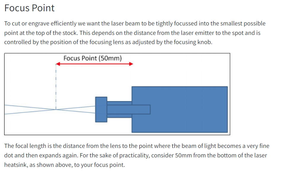
S Value Max is 255, $30=255, Cleaned the lens 3 times with windex glass cleaner and dried it with a cotton swab. I set the bottom of the heat sink to the material with a hard maple wood block cut to 49.98 mm to 50.01 mm, I then adjusted the laser using the lens ring moving it counter clockwise until it was a fuzzy blob and clockwise until it was a fuzzy blob and slowly tuned it in until I could get the sharpest dot that I could get. Keeping in mind with the settings S Value Max at 255 and $30=255 and 20% Power is barely visible with all the lights out in my shop. I will try the Power Scale Generator today. One last note, I did try some shapes with the $120 and $121 settings at 100 and the 200. The gaps did virtually disappear. Thank you for all your help and patience. I’ll send you photos of the completed Power Scale Gererator runs a little later.
1 Like
Good afternoon, I ran the Power Scale Generator. I don’t see any gaps in the text but then again the text is only 0.2" high. I think it looks good. The parameters are:
$$
$0=10
$1=25
$2=0
$3=2
$4=0
$5=0
$6=0
$10=0
$11=0.010
$12=0.002
$13=0
$20=0
$21=1
$22=1
$23=3
$24=25.000
$25=500.000
$26=250
$27=1.000
$30=255
$31=0
$32=1
$100=800.000
$101=800.000
$102=800.000
$110=2000.000
$111=2000.000
$112=600.000
$120=500.000
$121=500.000
$122=10.000
$130=500.000
$131=400.000
$132=100.000
ok
I did a test by increasing $120 and $121 from a 100 to 500 with good results in getting rid of the gaps. As I said previously, I set the S Value Max to 255 and the $30=255. The test looked good to me with the exception that I still can’t see the laser without darkening the room with the FIRE button pressed and at 20%. As you can see in the Power Scale Generator the 10%, 20% & 30% don’t even show any burning even at the lowest Feed Setting of 700 mm/min. I do have a video showing the laser was on but very faint at the 10% and 20%. It was brighter at the 30% but still didn’t have any trace of a burn.
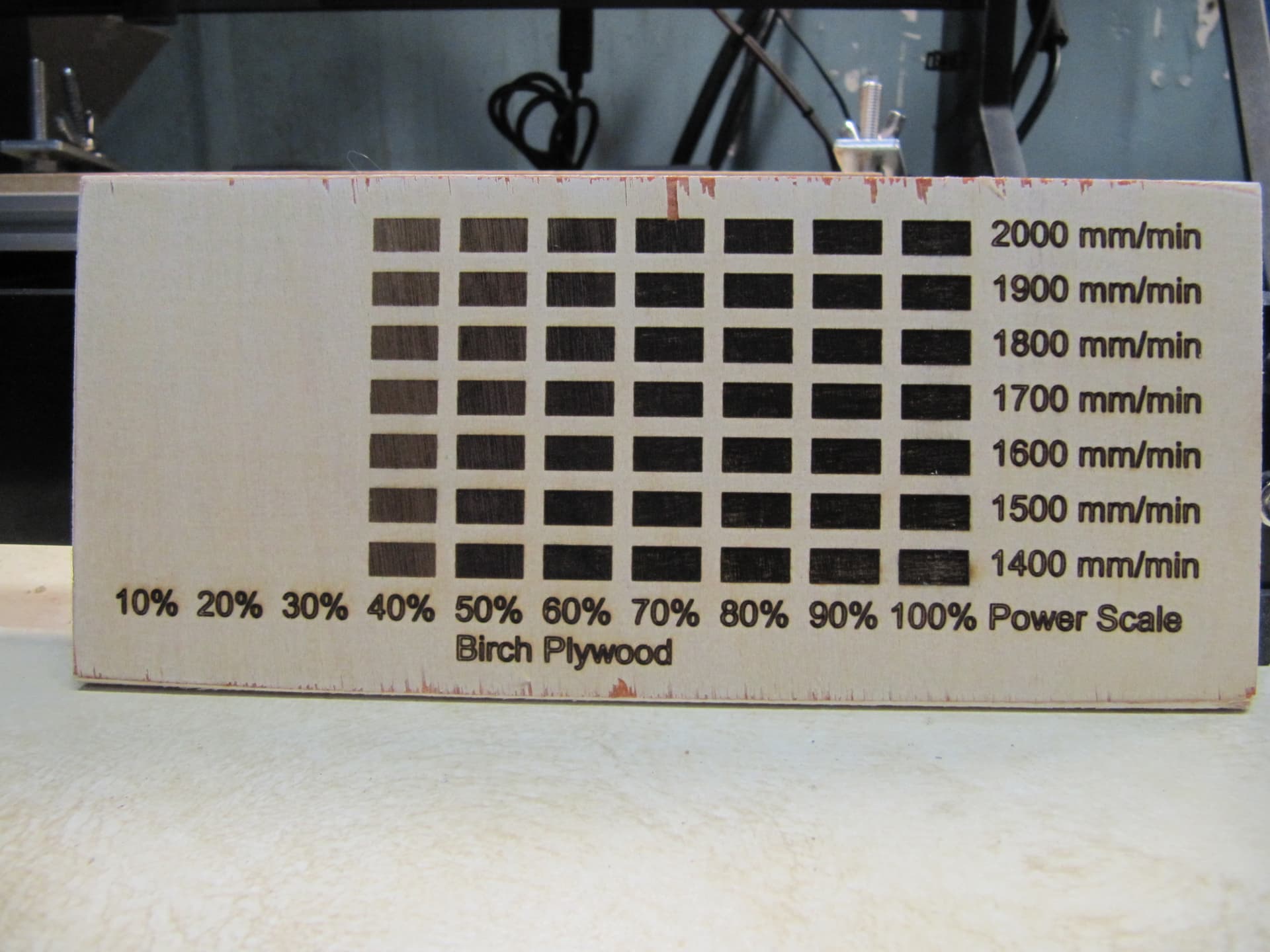
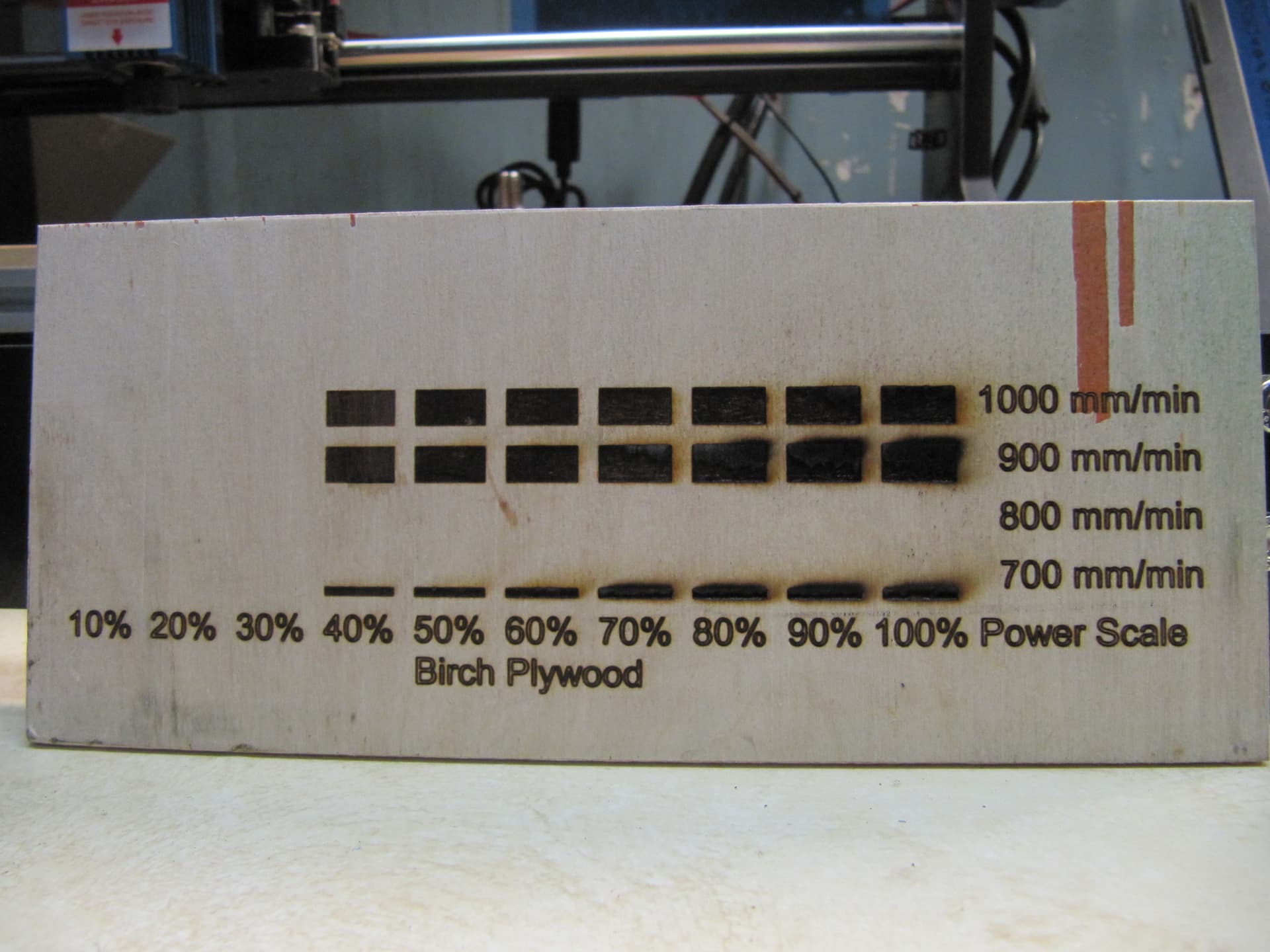
Very telling test. Things are looking better but there’s likely something wrong in the power modulation. The fact that you get no engraving at 30% or lower is odd. And it’s interesting that speed makes very little variation at speeds 1400 mm/min and up. You may want to try even higher speeds to see if you can get more variation.
Focus doesn’t seem to be a problem in the pics. Or at least not the main factor.
Are you thinking there is something physically wrong with the laser, the laser control board or the GRBL control board? Trying higher speeds would seem to cause, not only, the 10% to 30% power to not burn but might cause the 40% or higher to not burn. I’ll give it a try. I’ll have to run the test that James Dean shows for “Tuning GRBL Settings” to see how fast the steppers will go before they stall. I just glanced at that video and thought it pertained more to the Router Set Up more than the Laser Set Up. Thank you once more for your help. Especially on a Sunday.
I tuned my cnc3018 up by his work. Really ripped. It would walk all over the table and made all kinds of noises from the violent movement.
I’ve got three cnc3018 types, all have their spindles back on them. I used to run the original with a 30watt Neje with lightburn… that got me hooked and I moved to a co2… Rarely use the led, need to pick one and set it back up.
It’s a great exercise to understand the machine and the settings.
In the end I re-loaded the original numbers back, to keep it in one piece.
I’d really like to give you my speed results, but like an idiot, I formatted that disk by accident and it missed the backup, also my fault… I think you will be surprised at how fast it will run.
Good luck
![]()
Wait, do you have a separate laser control board separate from the laser module? Or were you just differentiating the control board part of the module vs the diode? My guess would be the board on the laser module but uncertain. There’s a chance it could be your power supply struggling at low currents. I don’t think it’s your GRBL controller since you’re obviously getting some control. Just seems like it’s not it’s not getting interpreted as I’d expect. Seems odd that it would be barely visible less than 30% power and then jump to pretty strong engravings at 40%.
I have the GRBL Control Board, The laser module, a laser control board and a separate power supply for the laser. All items were purchased from SainSmart.
I will be following James Dean’s video on Tuning GRBL Settings. I watched it today but didn’t get a chance to do it. Thanks, Bob
I’ve read through the manual listed on that page and noticed a few things:
- Are you using the included power adapter and plugging that into the control adapter? If so, I assume you have the 2 prong connector from your controller to the adapter?
- The manual indicates that you should have the bottom of the laser head module 60 mm from the target material. Did you do this before focusing?
- There is mention of power levels of between 10 and 20% for focusing so it’s possible that you just need it that high for a light to be visible.
- Do you have a meter or scope that you could use to test voltages into and out of control adapter? You should get a linear increase in voltage from 0-5V for 0 to 100% power.
Yes
I’ll give that a try but this is also their recommendation.
I didn’t see that but even at 20%, I have to have the room completely dark or I change the S Value Max to 1000 and use the “Fire” button. Then I put the S Value Max back to 255.
Yes I do. I’ll check that out as well.
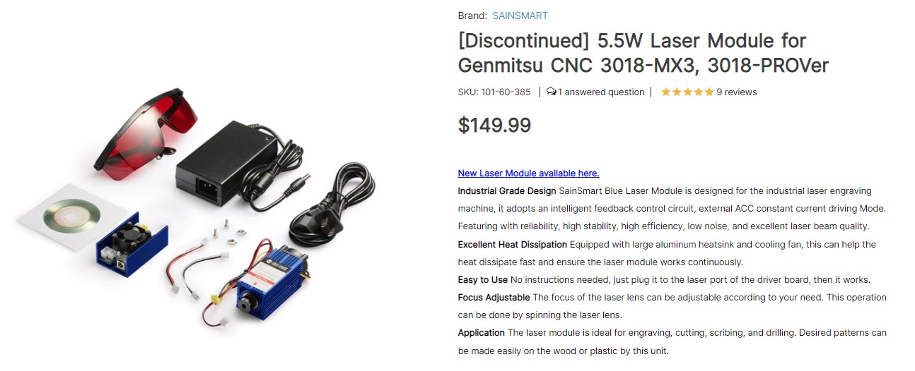
I like the comment in the description of the laser module kit. “Easy to use, no instructions needed, just plug it to the laser port of the driver board and then it works”. I bet you can guess what I am thinking now.
Isn’t the setting for the S value max 1000 for GRBL whether it’s an 8bit board or a 32bit board?
It used to be 256 for 8bit boards and 1000 for 32bit boards. In either case both the GRBL setting and LightBurn setting must match.
This is from the Lightburn Grbl setup instructions. If they don’t match, it will be an issue.
You might need to adjust your spindle max RPM value ($30) to match the LightBurn default (1000) or vice versa. The value in LightBurn is called “S-Value Max”, in the Device Settings.
I would think your LED would be working at 1%…
Just curious…?
![]()
1 Like