I have a 900 x 900mm CNC table and recently began using a camera with it per the LB camera support. LB v1.7.06. The camera I purchased is 8MP with a 10x zoom lens, which is perfect for a large table. It is manual zoom, focus, and aperture. I mount it on the ceiling and about 1.5m above the table and can lens zoom to the exact coverage of table size, wasting no pixels.
Today I tried LB V2.0 RC3 and can report that it has much better camera image capture resolution than 1.7.06 with same camera and settings.
Having recently installed a camera overhead of my CNC table, mounted on the ceiling, I needed a process to
verify and fine tune camera alignment to center of table from time to time since its not physically connected to the table, and
fine tune camera image scale when material height changes, which is often.
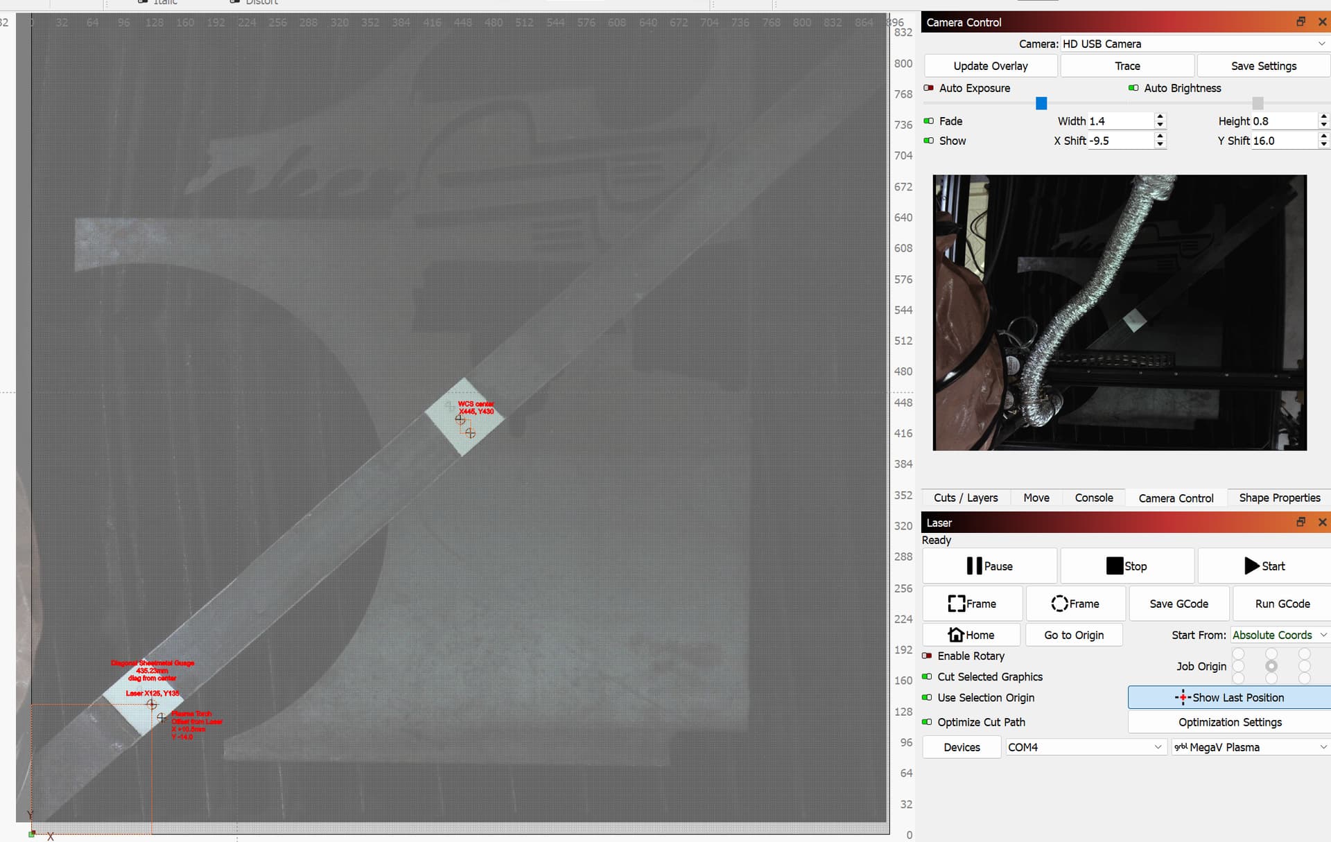
The good news is that the LB engineers anticipated such fine tuning from time to time and put the controls to do this easily on the LB Camera window. Well done!
The additional process element that I needed were two similarly easy physical reference points on the table, at new material working height (aka material thickness) without the need to rerun Camera Alignment tool in LB. Material height can vary up to 80mm across all three of the cutting/etching processes that my CNC can perform.
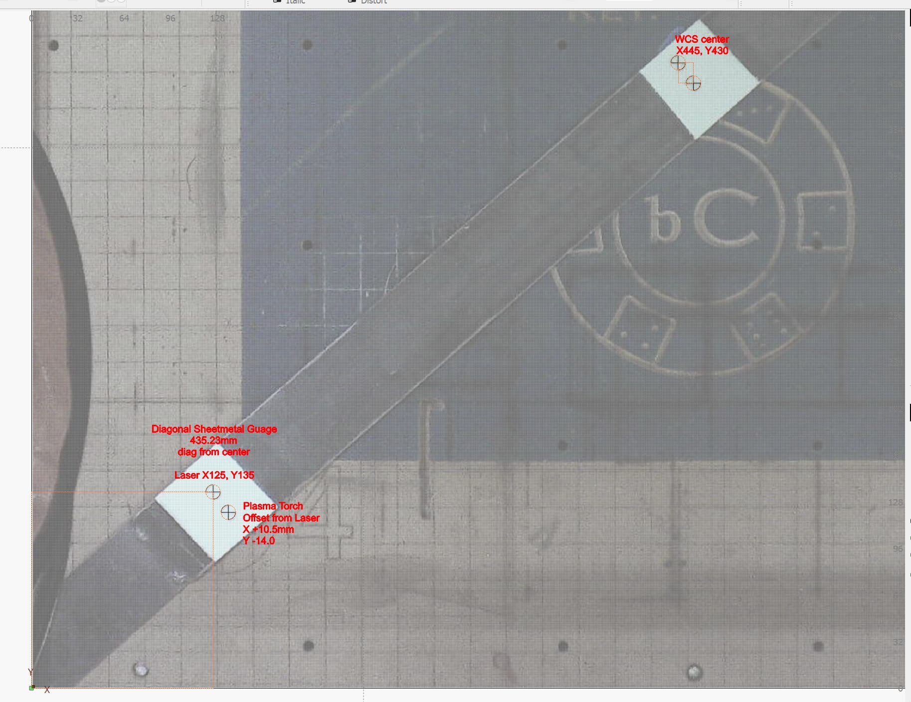
To solve this problem of easily fine tuning the camera alignment and scale under these circumstances, I built a ‘scale gauge’ with two points, a center table point and a rather random but fixed point on a diagonal line from center, in my case a distance of 435.23mm. The gauge is attached and thus registered on either end using two fixed points on my CNC Y rail frame.
Now I can drop the gauge in place at whatever material height I’m working with, in any CNC process. I first adjust the camera bed image via Camera XY Shift at table center point to the cutter head while at that XY coord control point, and then move the cutter head to the diagonal reference point and adjust Camera Scale. Done. I’ll post some photos of the scale gauge installed on the table later today.
I’m using LB on my semi-DIY CNC for laser, milling, and plasma processes. MillRight CNC makes the upper unit (rails, and drive train) and I’ve made the Z plate for quick change of cutting heads and the lower unit rail frame and table. The controller is grbl v1.1i 4 axis XYZA.
Thanks for sharing your setup and the pictures of your plasma!
I like the idea of mounting the camera on the ceiling and using an optical zoom lens.
As you know, it’s important that your CNC absolutely stays where it is. You can use the X and Y-Shift input boxes to adjust this.
For devices without a moving bed like yours, where the distance between camera and workpiece changes with material thickness, you can instead export your camera settings for the different material thicknesses and load the correct one when needed.
We have the relevant documentation here: Using a Camera - LightBurn Documentation
It’s worth mentioning, that the exported settings don’t include the adjustments from the Width, Height, X, and Y-Shift.
Agreed on all points. LB doc on this topic was very helpful.
The exporting camera settings method was not viable for my use cases, I don’t have many standard workpiece heights, its fairly variable across a range of 80mm vertical. Thus I needed a quick and easy way to re-establish the workarea center point (with offsets for the attached cutting head control point) and to establish another point distant from center to establish scale. I already had fixed registration points on the CNC workarea frame, so I just used those to locate my diagonal gauge.
Thats a great solution if it works for you.
I was wondering, since your camera-surface distance is about 1.5 m, the effect of the misalignment with different thicknesses is less pronounced due to the narrower field of view. Because of this, depending on the accuracy you need, it might be enough to do only 2-3 calibrations over the range of the 80mm and load the closest one.
But again, the markers are a clever solution.
Something similar is in the works and the Alignment process will be much easier in the future!
You can get a glimpse at this in the Release Candidate of version 2.0. The Head-Mounted camera alignment is still in beta but you can get an idea of where it’s going.
agreed, but I had trouble with that approach in that I still needed a work area center point reference to verify alignment given my camera and table are disconnected, and its not ‘if’ the table moves, the situation I’m guarding against is ‘when’. So the easy solution was the diagonal sheetmetal scale. I had been using a smaller scale gauge reference point 100x100mm from front left corner, even easier setup since my operator station is right there, but I found that lacking the center point reference, verification, and usual adjustment with XY image Shift, all of those were important missing process elements.
re. accuracy- its addictive. Once I got 2mm at the extremes, I wanted 1mm, then I wanted 0.5mm, but at that point the image resolution was the limit. Except for LB V2.0 RC3, surprisingly that image resolution is much better, so less than 1mm accuracy seems to be attainable. That is amazing in 900x900mm work area. I also found, as the doc states, that during camera lens calibration is very important to keep the april tag image exactly perpendicular to the camera lens, (or perhaps consistently at the same slight angle plane (if any) near perpendicular) that made a huge improvement in scale accuracy. Workpiece height (aka thickness) was still surprisingly important to scale settings for good accuracy.
re. LB v2.0 RC3- I couldn’t explore the new camera alignment process because of apparent bug in general position reporting in the Move window, Get Position results are not correct. So any programmed motion is wrong or interferes with limits, only jogging works somewhat. I sent a bug report to betasupport@lightburnsoftware.com
No word yet.