Hi guys,
I have been trying to make a few coins with my laser, the designs come off great but have some problems still. And I am quite lost on how to fix them. To be honest.
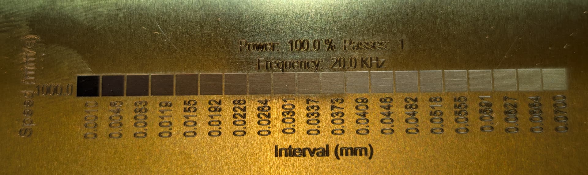
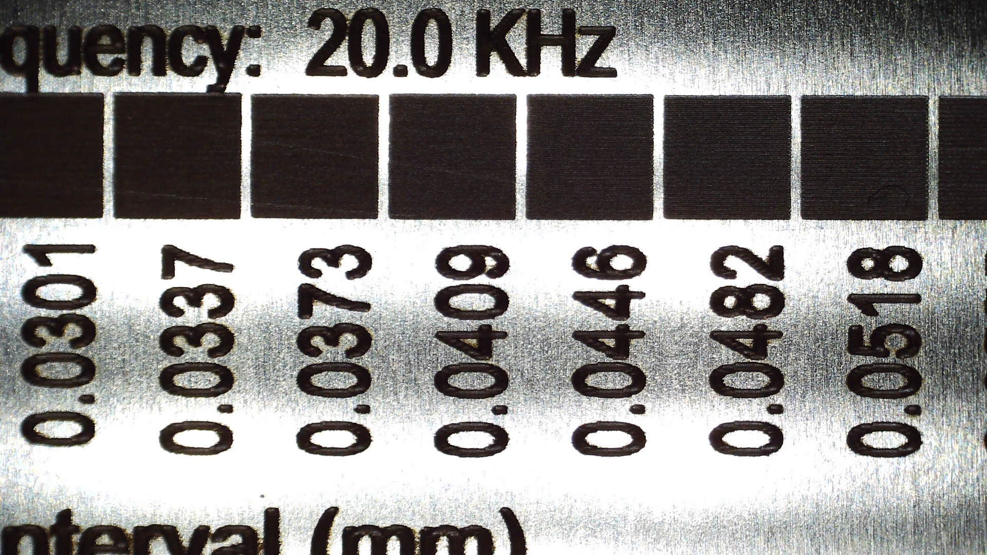
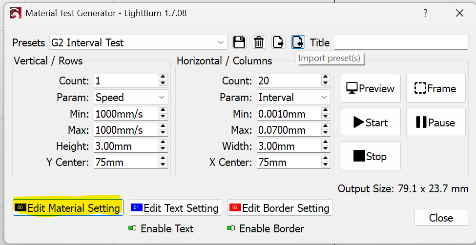
- The designs are good and sharp, but upon closer inspection and cleaning you can see a quite distinctive raster or grid pattern in the areas that have been (deep) engraved. I have tried to toy around with the dot width and resolution (lines per inch) etc, but nothing really seems to help. Going normally with settings like 6000 dpi and a very small dot width. But the results are almost the same as going with 1000 dpi. The only difference is that the machine takes about 6 times longer to finish, sometimes it runs for a whole day.
I might add that it is a fine pattern, but still makes it a pain to polish, and in some cases you risk damaging the details if you go on too harshly on the piece to get a mirror shine.
I don’t have any illusions that a laser could do something that is like a mirror, but at least a bit better. I will see if I can get some photos uploaded. But in the meantime I think you get the picture. Anyone had any luck trying to get rid of these patterns in the settings?
-
The edges to the engraved areas almost looks burnt or melted, extremely hard to clean without damaging the coin details.
-
Let’s say I do a grayscale design with just a 1" black box on a white background, that means it will be a, let’s say 1" square engraving made into my material, which in this case is brass. however seeing it at the bottom, the “walls” of the square are bending towards the centre giving a round look to it. I can’t really understand why this happens, as there is no gradients present when this simple example design is engraved. Same happens to small letters or numbers. They are true to the design on top but widens towards the base like a mountain. Is there a setting for this? I suppose not?
Very happy for any help at all!