Recently received my G2 Max, and I have Lightburn with a Pro license.
I followed the somewhat sparse instructions to add the machine. I have an image imported for a test burn, but when I do Live Framing it almost behaves like it is actually trying to engrave vs. Live Frame, but at an incredibly small scale. When I start Live Framing I see the white light indicating that the fiber laser is firing, but essentially only at where the red focal dot is. It does mark the surface, but literally only like a pin prick.
I am able to successfully use the “Red” function in the included Glaser software if that helps.
I followed Gweike’s tutorial and the manual’s instructions, which were pretty much the same. There’s not really any difference for Mac, you just have to import the Windows BslCAD.cfg file.
Did you check how the source is defined? This is in the device settings.
If you have a different source, it may not operate correctly.
First thing, with a new machine is to contact the vendor. They should help you get it working. If it works with their software, it should work with Lightburn.
What white light are you seeing.. mine is red, have never seen a white light on one of these. I don’t have one of these machines, mines a JPT mopa.
Scary. This should not happen. Can you send your exported device .lbzip file, so that we can see, which setting might be causing it to fire while framing?
In Gweike’s video, they used the .BslCAD.cfg file and this didn’t populate any settings. This is why they further instruct to type in the settings from the screenshots of the thumbdrive.
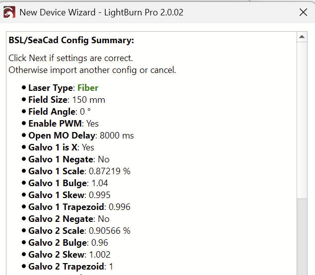
When you import the correct config file, it will show a summary of the contained settings like this:
For my Gweike G2 Pro 30W, the correct config file to import was instead the LmcPar.cfg!
I’m aware that this process can be confusing. We encourage every manufacturer to instead provide a User Bundle containing all the needed settings.
Let’s try this: We exported the settings from our G2 Max 150mm lens to this .lbzip file.
Download and import it by dropping the file to the LightBurn work space. GWeike_G2_Max_50w_20250219(1).lbzip (1.7 KB)
Ugh. I watched the Gweike tutorial again last night, and I retraced my steps, and I believe I forgot to add the device parameters after creating the device. It is now working as expected, except the text is rotated 90º clockwise. I’ll figure that out…
Edit-
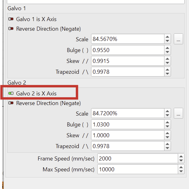
…and figured the rotation out. The device parameters image provided by Gweike shows galvo 2 as the X axis, it should be galvo 1,
The instructions in the video might not apply to your specific machine.
I’d suggest using either the screenshots from your USB stick for the Scale, Bulge, Skew and Trapezoid values, or the config file I posted. if you are also using a 150mm lens.
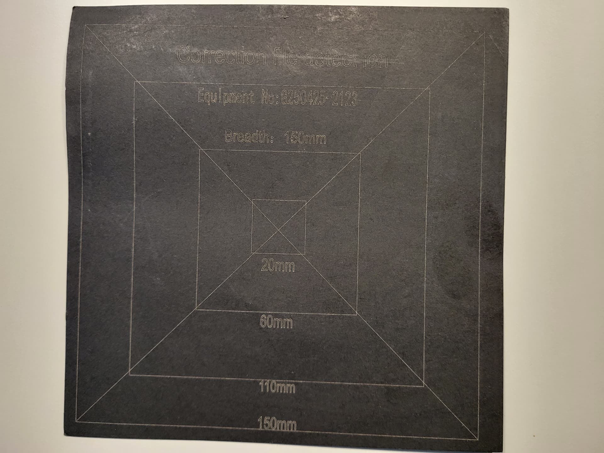
OK, the G2 came with a black piece of paper with 20mm, 60mm, 110mm, & 150mm boxes so I used that.
I created a square and increased the size by those increments.
the 20mm square was properly square and dead on for the measurements.
The 60mm square was properly square, but was slightly long on the Y axis, good on the X axis.
The 110mm square was not properly square and was also long on the Y axis. The lines along the Y axis bulged outward slightly, the outer limits of the bulge were 110mm, at the corners it was less. The X axis lines concave a bit.
150mm had the same distortions as 110mm, but more exaggerated.
I did this before you posted the timing values, I tried changing those but it didn’t seem to make a difference.
I’m not sure I follow you here. Are you saying you are using this paper for measurements only?
If you can send us a photo of that, it would help me understand.
As I mentioned:
My question about measuring the projection of a 100x100mm frame was meant to confirm this.
I placed this on the base, centered on the red laser. I then used live framing with the incrementally larger boxes as described before.
I had previously downloaded you .lbzip file and imported it. I failed to change the device settings to match the included reference images, I have done that now.
Now all the squares are in fact properly square, however…
The 20mm square is the correct size, but appears to be about 1mm down on the Y axis from the center dot.
The 60mm square looks to be about .5 - 1mm short on the Y axis, and and about 2mm up on the Y axis from the center dot.
The 110mm square is about 1.5 - 2mm short on the Y axis, and about .5mm short on the X axis. It also appears to be about 2mm up on the Y axis from the center dot.
Getting closer!
Edit-
I did the same test with the GLaser app that came with it, and the offsets and size discrepancies I listed about are the same.
Thank you for the picture. Now, I do remember seeing this paper. It went straight to the bin, because I didn’t trust the “Breadth” to be very accurate:
To measure the accuracy of the Scale value, you only need one reference distance at a large size.
You can use the paper, if you are sure the dimensions are correct. (Use a ruler to measure the sides of the squares)
But ignore the center point! As you can see in the marked circle, the squares are not properly aligned.
Just frame a square of a known size, and measure the length of the sides.
I’m curious to know how accurate that is with the file I sent you.
You’re probably busy engraving and trying out different things Fiber lasers are fun, aren’t they?
If you are happy with the Bulge, Skew, and Trapezoid values, leave them as they are.
I’m posting a link to the full Galvo Lens Calibration for completeness.
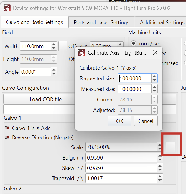
To fine-tune only the Scale values for more accurate dimensions, you can do the following:
Engrave a rectangle of 100x100mm (You can use the black paper)
Open the Device Settings and click on the three dots next to the Galvo 1 “Scale” field:
I’m not sure, I follow you here. Can you explain what you mean?
The Gweike G2 has two red dots. One is through the lens and should have been aligned to the laser source at the factory. (It’s entirely possible, that this location does not correspond to the center of your workarea.)
The other red dot is pointing down at an angle. The angled red dot is intended to converge with the main dot at the focal length.
See, if this helps:
Or are you saying the red frame is not where the laser is engraving?
You shouldn’t have to do this, but in this video, we describe how to set a red dot offset:
I need to make sure the center dot is actually in the center of the engraving area (75mm X&Y).
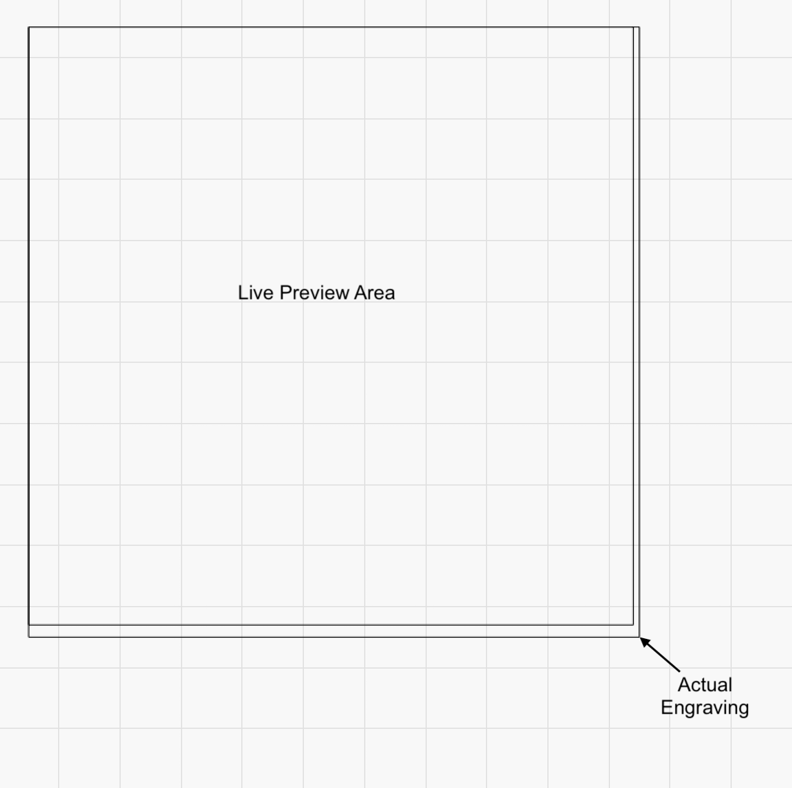
I need to ensure that the Live Preview and the actual engraving are the same. Specifically, I know that right now the engraving is exactly 100mm x 100mm, but the Live Preview is smaller by 2mm on the Y access and 1mm on the X access. The Live Preview is also not centered on the engraving, it is indexed off the upper left corner of the square, see the pic below.
The video got my Live Preview aligned with actual engraving. The center dot and dot used for live preview are not perfectly centered, but I think I can live with that.