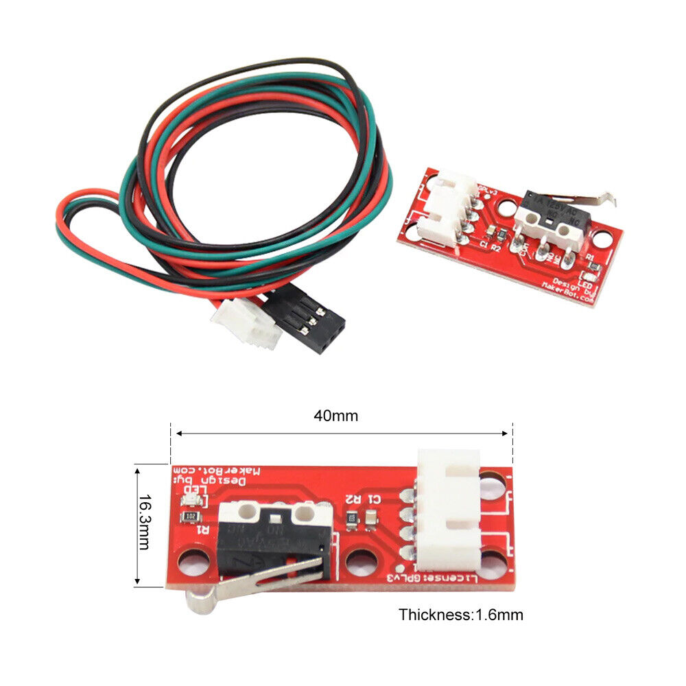
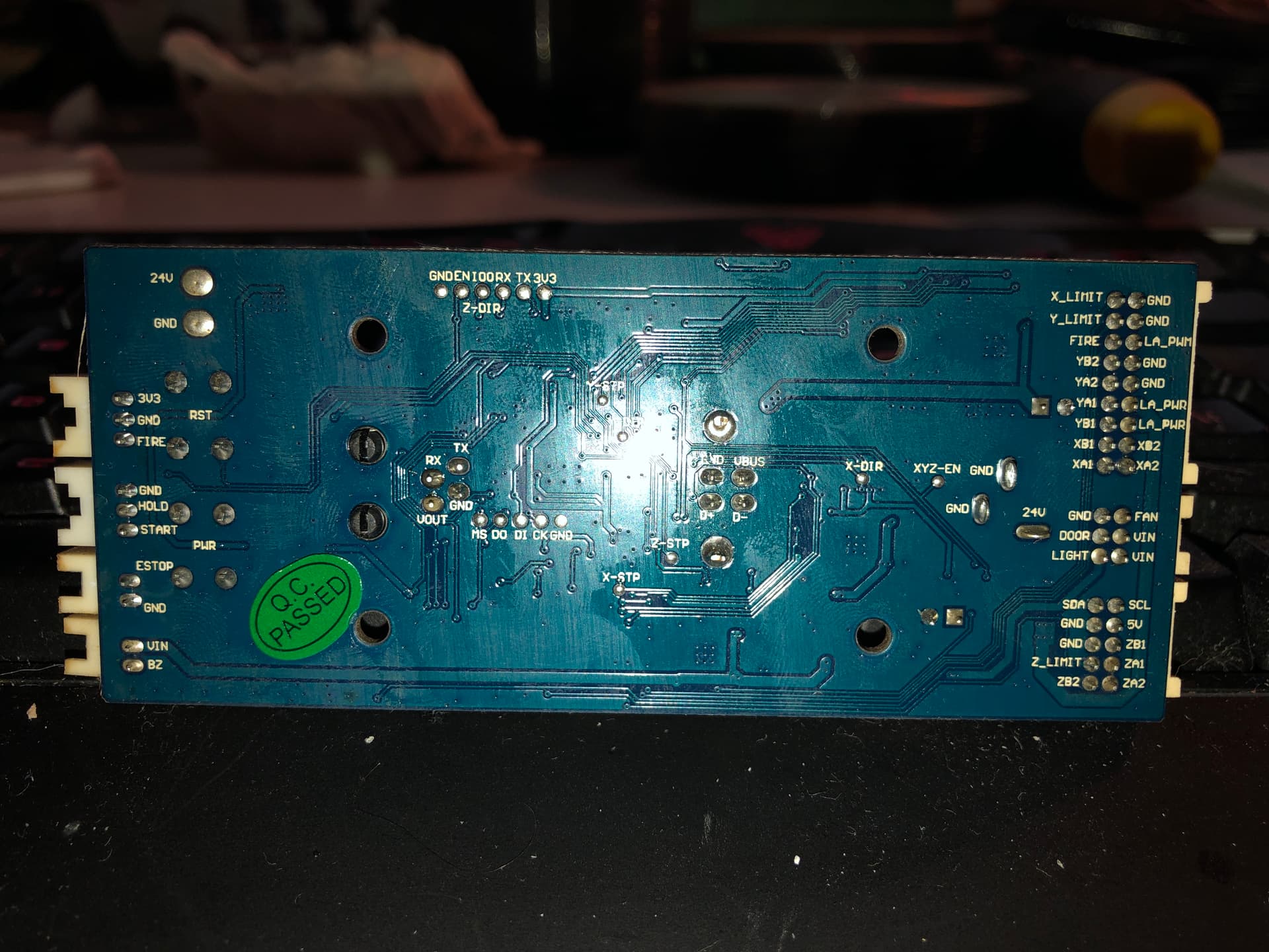
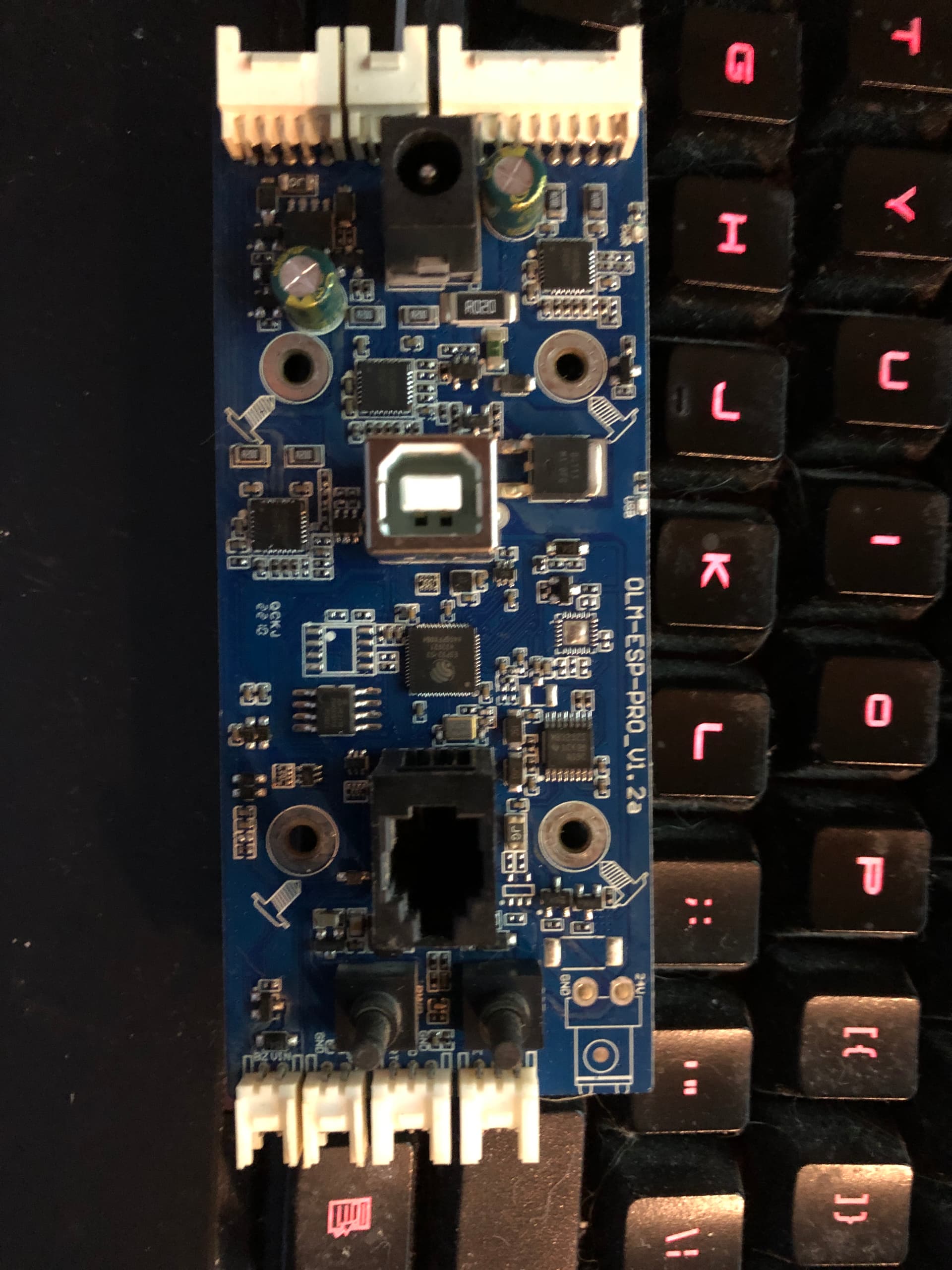
Have had an Aufero Laser 2 for about 6 months and love it but the lack of limit switches is a constant irritant so I bought two limit switches (Makerbot) and installed them on the laser. BUT … I cannot see where to wire them on the motherboard currently installed. Pics of the limit switches and the motherboard are attached.
I have read multiple articles and viewed multiple videos on this and am comfortable with what to do but I just do not see exactly where on this motherboard it is supposed to go.
Any help/suggestions are appreciated. I did put a service tag into Ortur support and while I got an acknowledgement, I also got an email basically saying that the 2 main folks who do the support have quit thus I am reaching out here.
On the bottom of the board you will see X-limit, Y-limit, and farther down is Z-limit.
Unfortunately, the board appears to be designed for a particular manufacturer. Rather than having separate plugs/pins for the limit switches, they are integrated into larger connectors. This makes it more difficult, but not impossible to wite up the switches.
There is a gentleman on Etsy, his name is Ihab (IhabLaserDesigns - Etsy), and he makes custom cables for Ortur brand lasers. I had him makes a cable for me when I swapped out the OEM controller on my OLM2 Pro for one of Tim Rothman’s B-N-B 3 mainboards. I would contact him and explain your situation, and what you’re trying to accomplish, and see if he can make you a new cable that will allow you to plug it into your limit switches. It’s worth a try. His custom cable worked great for me.
I did exactly that at the tail end of last year. I wasn’t happy with the Ortur motherboard so I replaced it with an aftermarket board made by Tim ( Products | LaserUpgrades ) and I’m very glad I did. I just looked on his site, and he seems to be out of stock at the moment, but if you were interested in going down that path, I’m sure you could contact him and see if he was going to start up production again. They aren’t cheap but they have a lot of great features built into them that make them worth it.
Appreciate the response Paul. I actually have a spare 32 bit board from an Anycubic 3D printer but I still think the current board will work if I can figure out where to wire it. I can see the x and y inputs and associated grounds but the end stops are three wires and I am not seeing something that indicates where the signal goes. Thank again… Steve
I had switches similar to yours and on mine the third wire was to light up the LED on the board (near the switch) when triggered. I didn’t need that feature, so I just took an ohm meter and figured out which pins were from the switch contacts. Hope this helps.