Let me ask first, is what is displayed on the ammeter during a burn or cut relevant at all?
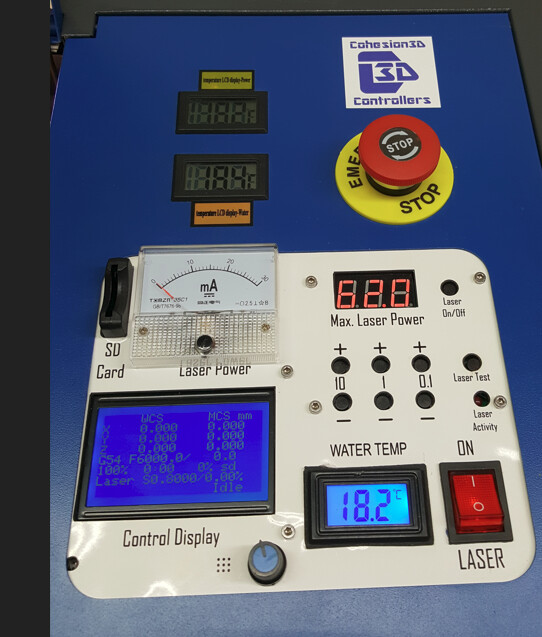
Here is my example, I have a K40 laser. I have my digital setting set at 62 which when I press the test button gives me a maximum of 15ma on the ammeter. So that is my max output on the hardware.
Now I setup a simple circle cut in LB with a speed of 20mm/s and a Max Power of 50%.
Now when I run this cut at 50% for the duration of the cut the ammeter shows 12ma output (more like 85%).
Wouldn’t the expected ammeter reading be more like peaking at 7.5ma max ever at 50%?
Don’t know what I am missing here about how this works.
Example 2, a simple raster image engraving, set at 100mm/s 10% max power.
When it runs the ammeter shows it fluctuating between 0 and 10ma.
How can it be getting as high as 10ma when it is set to only use 10% of the max power?
Should be more like 1.5ma on the meter.
If I have understood your question correctly, then the answer is yes, knowing what corresponds to your settings in% to mA is very important.
As you yourself write, adhere to a max effect to avoid burning out the tube. Max output for a 40Watt varies slightly according to one’s temperament, my max setting was 16mA.
By documenting your real output values in mA, it gives you a reference to see the condition of your tube.
By your “documentation” itself, you will also find that the effect of your tubes is not linear. Therefore, general algebra does not fit here. (10% is not 1.6mA) You need to figure out the relevant% settings that correspond to your tube and its mA to be able to use the right values for your projects.
You should expect that depending on the quality and operating hours, your tube will become weaker and weaker. Even if you do not use the tube, it will weaken over time. To be able to decide when it’s time for a replacement tube, you should preferably know your current power in mA.
When engraving, you can not use the reading of your ammeter, it is too “nervous” to look at. Use when cutting across multiple seconds / minutes at a time - and write it down in a list of the corresponding values from LightBurn (%). I do it on a regular basis to be able to keep an eye on my tube and to understand why the same setting of a project is not “good enough” after half a year when I run it again.
So other than figuring out what your max hardware setting is on the digital meter and the ammeter, the ammeter is useless after that point. What I don’t understand is what is the point of the power setting in LB then. If I have my hardware side set that it can never go over 15ma, what are the power max values relevant to then in LB if I set my max power for a cut layer to 10% and my ammeter is pegged out at 12ma during that cut
?
Can your C3D lock the max output of your K40?
To your question regarding power setting in LightBurn, you need to find out for yourself what corresponds to the percentage scale. But as I said, even if you adjust your PSU to fit with LightBurns 100%, this scale will not be linear. 50% will not be 50% of the output power of your tube.
With my MiniGerbil I could not determine the max output of the PSU for the tube. In LightBurn, about 55% was my max output power corresponding to 16mA. When balancing my K40, tests showed that at 16mA-17mA the peak power of the tube had been reached, then the efficiency dropped slightly.
I would be happy if there was a built-in option in LightBurn, to be able to “calibrate” one’s max output power to 100%, that is, my 16mA should represent 100% (without fiddling with the PSU). It will still not give you a linear curve but a better spread.
I am not using a C3D board any more, I just replaced that with a LX4 board (runs GRBL).
Again, I really dont see the point of the Power max in LB if you can never use it on a scale. Like right now I just cut out a simple square at 20mm/s 20% power but when I started the cut my ammeter showed the power was maxed out at 15ma for the whole cut. So, if it boils down to in LB your real scale is say 2% to 25% and 25% means 15ma then how does it make any sense to have 26% -100% even an option?
Let me try a little more instructional example. Let’s say I have my laser its max is 15ma, no matter how hard I push it, it can never go over 15ma. Now I have my muscle car it has a max speed of 150mph and no matter how hard or far I press on that gas pedal it’s never going to go over 150mph.
No if I get in that car and press the gas pedal to half its range (50%) I am going to go about 75mph.
If I set that laser to use 50% of my available 15ma but its still going to use 100% = 15ma.
Now how does that make any sense?
It amazes me that you reach up to 15mA at 25%, that’s half of what my K40 scale showed. How much Watt is your PSU on?
You wrote that you have “locked” your K40 at 15mA, how did you do that? or have I misunderstood you?
The only real way to “achieve” 100% scale in LightBurn is to regulate one’s PSU, as far as I know.
But this is not an option for a standard K40.
Well, I have an ammeter installed, I set my digital reading on the display to say 50, pressed the test button on the panel, view what the output was on the ammeter, then bumped it up twill the ammeter was at 15ma and it stays at that setting which ended up being 62 on the digital meter.
I have a Ruida and a couple of grbl machines don’t know what options are available on your controller… but…
Not having a K40, I’m not clear on the ‘max laser power’ control use or how it works, hardware wise.
On my Chinese 50 watt laser, I set ‘max power’ at the lps… That seems to make things work out.
I’m sure someone will correct me if I’m wrong about your controller.
I think in simple terms, if you set 50% power, Lightburn tells the controller to generate a 50% pwm output signal or whatever percentage.
What the controller tells your laser to do, I think, is out of Lightburns scope.
Many controllers modify this when the speed changes and can limit it to a certain max percentage.
Same as with the max X and Y axes speeds, they are speed limits that exist in the controller for the machines protection.
What does you controller do with a 50% pwm signal.?
ANY mechanical meter will read RMS values or an average, same with the mA meter. A digital meter has a ‘sample’ rate and it it samples when the pwm is off (low or no current) that’s what it displays…
As I said , if I set it for 50% and my max is 100% = 15ma and I try and cut out a circle or square it will cut it at 15ma on the ammeter when it should be around 7.5ma (50% of 15ma).
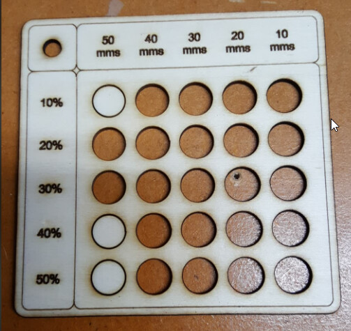
Yea that is kind of what I am expecting but it’s not working like that at all it seems to be all over the place and random. Look at this cut test image for example. Look at the first vertical row. Why would it cut out the circles for 20% and 30% power at 50mm/s but not cut out for 40% and 50% for the same speed. And you can look at all the other holes it cut out mainly because through that whole thing it was pegging the ammeter at 12 to 15ma for all of it regardless of what the layer in LB was set for.
I have the max set at 15ma using the digital display and buttons and the ammeter that I have installed.
The hardware has been working fine up till today when I swapped out the C3D board I was using with an LX4s from VMS.
LX4s is sold on FB group from company call VMS. (VMS Laser Accessories).
It’s a Grbl based board. The controller is configured as instructed by the Electrical Engineer that designed it.
This is a subject that I have been trying to better understand. How exactly does one check the pwm output with a voltmeter? The more basic the explanation, the better. Thank you very much.