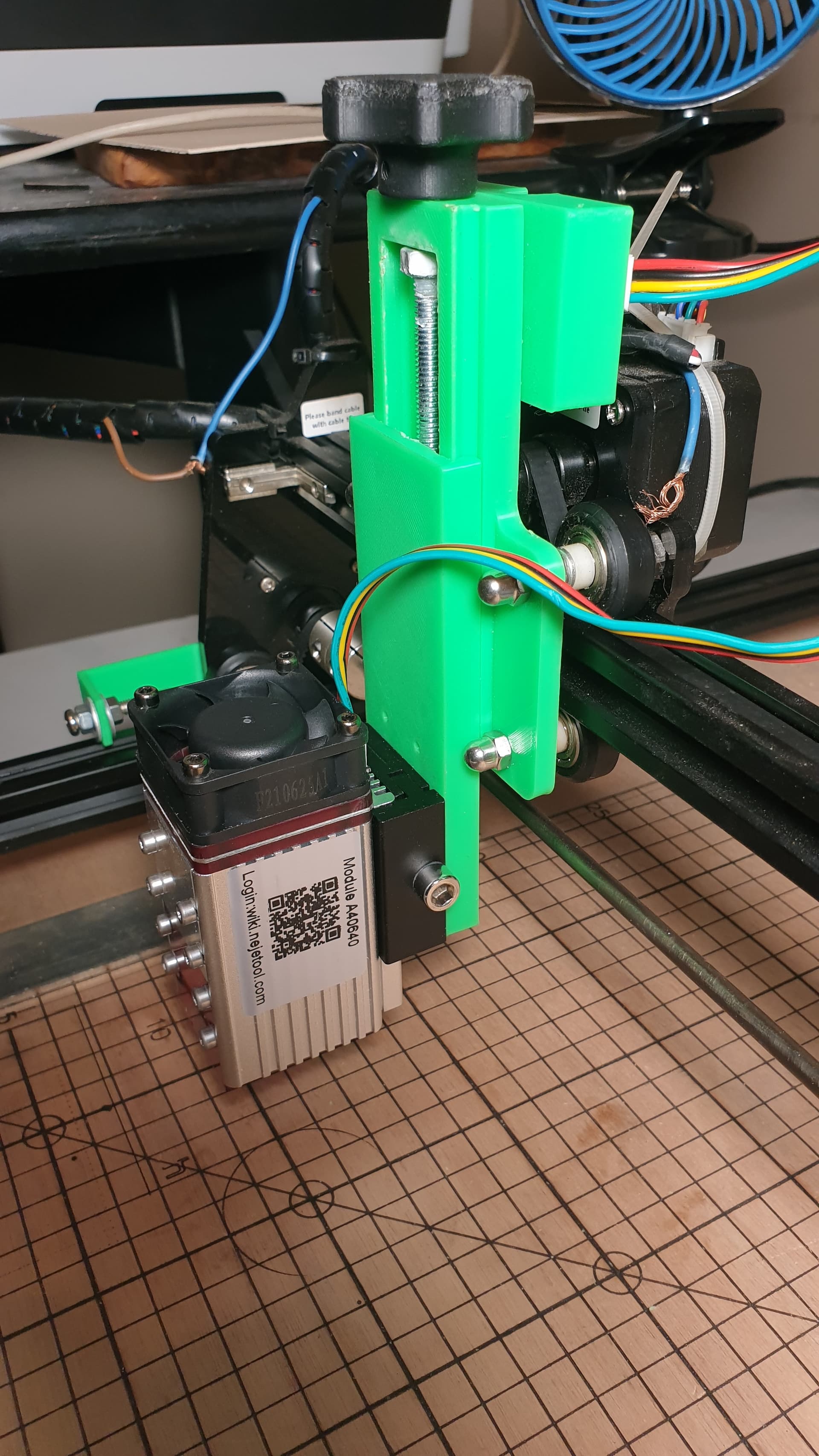
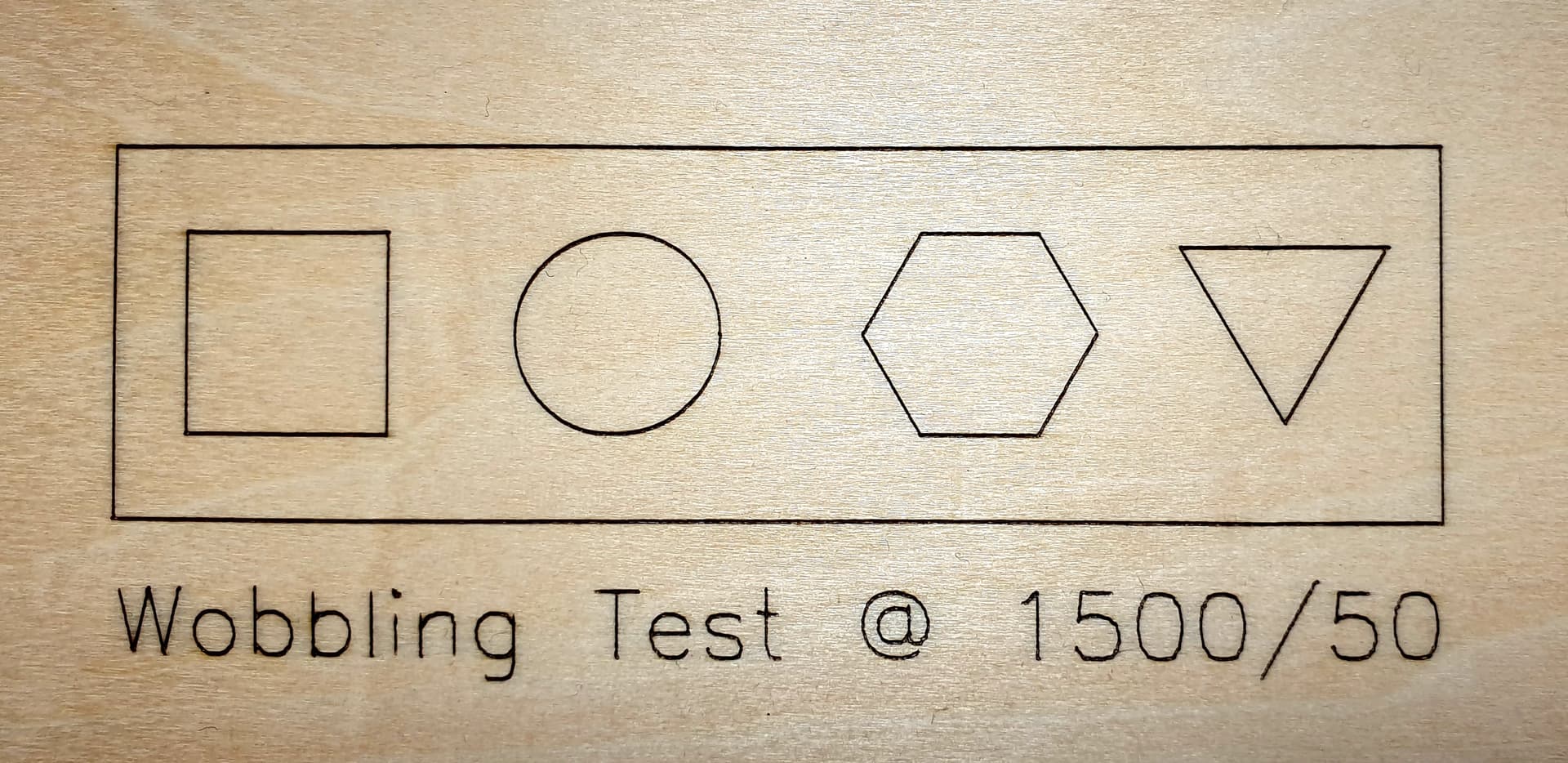
I use an Ortur Laser Master 2 (not pro) and i’ve mounted a Neje A40640 on it. I am very pleased with the new laser module, however I do have a wobbling problem with the OLM2 machine. Some pictures will tell you far better what i’m talking about :
I think the wobble has to do with two things which are interdependant one another :
the fact that the module is very low compared to the original module’s position (because the Neje has a fixed focus length of approx. 18mm from the heatsink).
So the mass is lowered, and all of it is naturally off-centre in regards to the X-axis gantry.
the wheels on either sides of the X-Axis gantry aren’t extremely tight on the gantry and hence, some play occur. I couldn’t upload here the small video i’ve made to show this play, but you can see it there : https://streamable.com/61th8s
As you can see, the play is quite big and comes from the unit on wheels rather than the 3D-printed Z-Axis (which is very well tightened and solid).
Could you advise a way to kill this play so that my engraved lines don’t look as if my OLM2 had Parkinson ?
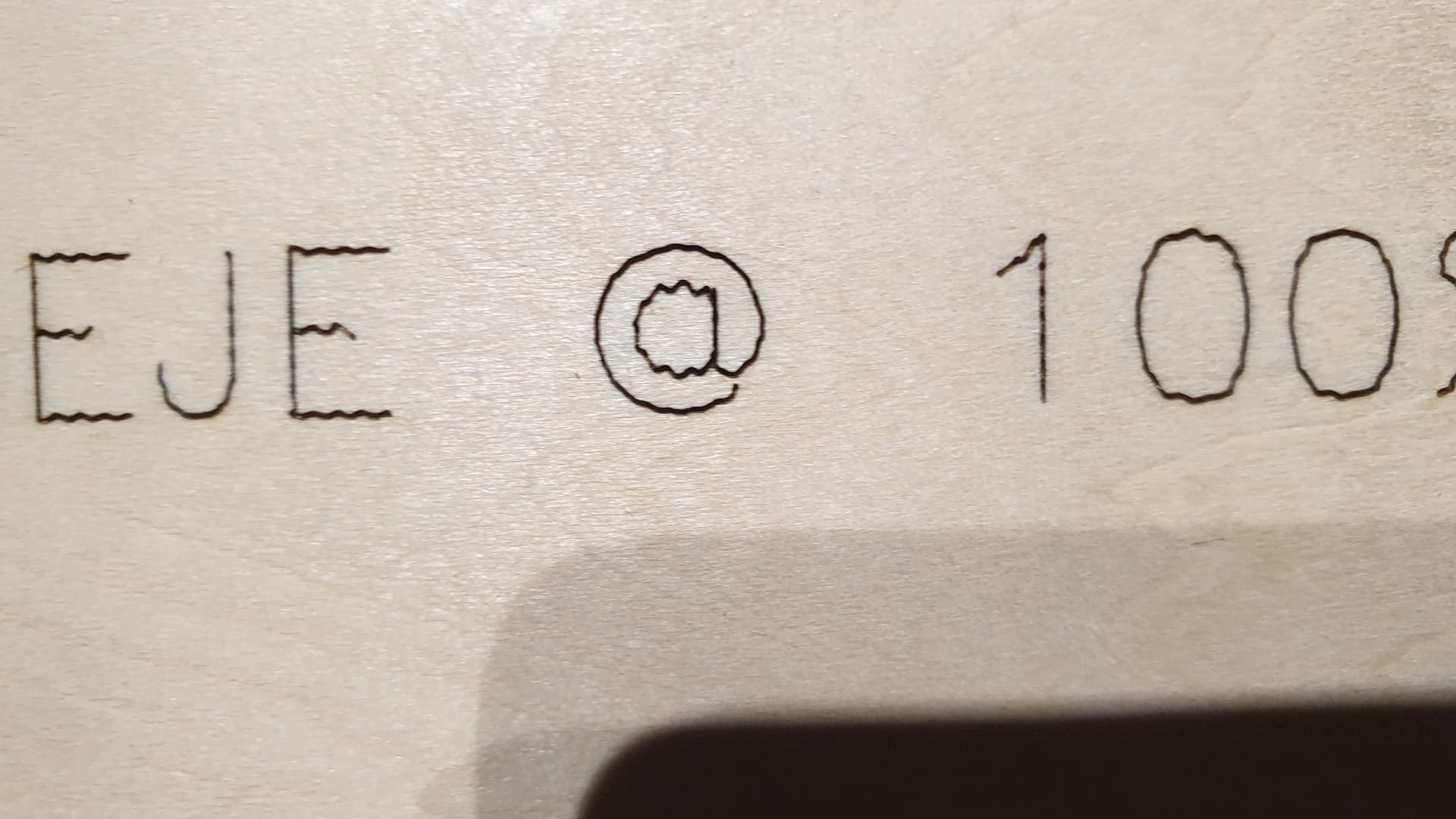
I mean, look at this marvelous “@”
Your problem seems to be physics.
You added basicly a pendulum to your machine
You can validate this by reducing the accelerations to a very very low vallue like 200 and reduce also the speed of the machine.
(granted this is counter productive to the why you bought the more powerful module on the first place)
There are things you can do. but we need to verify 1st
a) Eccentry wheels on the X gantry are adjusted? The 3d printer adapters tend to not be very acurate and might “spread” the screws lifting the wheels from the rail, you need to copmensate. Any slack between wheels and the rail (on the x)
b) What if you “lift” the material to the module instead of bringing the module to the material
Raise a test material as high as it can go to clear the X and the module. Then run a small test
c) what speed/Power settings you using?
Thanks for the quick reply. It is indeed physics-related. Although i haven’t testet yet, i’m quite positive that if I drastically reduced acceleration and speeds, and if I set a delay of say 100ms at the start of each burn, it wouldn’t wobble as much. But as you said, it’s sooo counter-productive…
For your questions,
a) This could have been it, but my 3D-printed adapter does not spread the screws, because I filed the holes a bit so that they fit very easily; no need to force in the slightest. So I actually dismounted it to see if there was slack even without, and there is indeed a tiny bit, which in my opinion is cause of the problem. If I push the bottom wheels up, there is no play at all and my problem would then be fixed I think… The orgininal module being well-centered in regards to the moving unit, this was no issue at all. But the Neje being so down, it makes things problematic because it creates, as you rightly say, a pendulum.
→ Is there a way I could have the bottom wheels pushed up, somehow? A way to “squeeze” them onto the gantry ?
b) Yes lifting the work plane up diminishes the problem a bit, but does not erradicate it because of the mass of the Neje, and the fact that it remains more off-centered due to the thickness of the adapter.
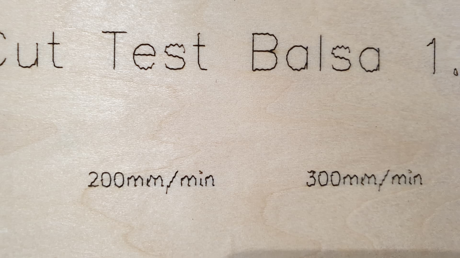
c) On these photos I was 1500mm/min and 50% power.
→ What is your opinon and the other solution of upgrading to an OLM2 Pro machine ? Would this problem remain, because I could then have the Ortur-made Z-Axis instead of a 3D-printed one… So the whole thing would be completely stable, wouldn’t it ?
The way you have it set up its a bit tricky you have too much mass above and below the attachement point
There is something you can try, which is a try only, add mass to the back to counter balace it. like balaster
Heres the main problem
One is trying to fight 3 “deamons” at once
You bought a more powerful module to gain speed
But by its specificities the module needs to be held Low
So you are fighting physics with physics, which is a whole can of worms
Would be slightly counter productive to have a more powerful module, but ending up to move slower because the physics.
I would first of all remove the whole 3d printed part, and attach the module bare
LIft the material to the module.
Is this better?
If so you might have to compromise on your lifting mechanism
You might have noticed most brands make them simple and limited, for a reason. Not necessarely because its “cheap” but because mass causs the problems you are facing.
Think Co2 machines. the head is made as lightwaight as possible too for this very reason
Yes it is exactly as you say. I fight many demons at once and each one makes the other worse. But i remain optimistic, there are solutions. One is, as you suggested, to raise the working plane and ditch the Z-axis adapter. Since the Neje module is movable in the Z direction, I could use that if I ever have to work on thicker materials.
First things first, I’ll give a go on these eccentric nuts (I had no idea they had this function, that’s awesome!)
I’ll then try to add a countermass, if the eccentric nuts don’t solve it.
The thing is, i’ve seen quite a lot of YT vids with guys using Neje modules, and they really don’t seem to have my problem, even on an OLM2 standard.
But then again, they don’t have to use a 3D-printer adapter that off-centers the whole thing…
See this one for exemple : https://youtu.be/ono1Wv2KaQE and the fitting is clearly seen at 04’40" into the video
I’ll let you know if the nuts correct things or not.
Thanks again for all your detailed answers, this is much appreciated
Your issue mostly is too you doing vectors
if you were doing side by side raster engraving, and added say 2.5/5% overscan you would have no problems at all
These deamons surface at times in some specific jobs.
Also remember, most people dont show you their trash bin. THe failed prints. (Which is naturally obvious, but something to consider)
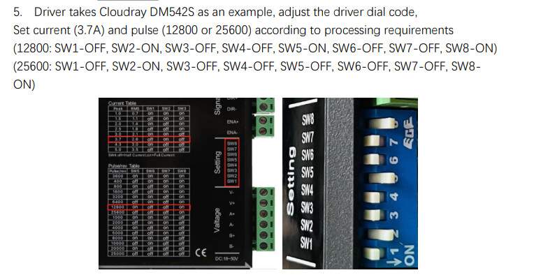
1: It is recommended that you first check whether the mechanical connection between X axis and Y axis is firm, or whether there is a gap
2: Check the motor Settings of X-axis in the control system to see if the pulse number is inconsistent with that on the driver
Thank you Anoxin, this looks really interresting !
However this is way above me ; I don’t even know to what these screens refer, nor where should I look to see this. Is it inside the stepper motor? So sorry for this noob question but well, it’s the first time I see this…
Anyway, you actually set me on solving my problem even further with your sentence ‘1: It is recommended that you first check whether the mechanical connection between X axis and Y axis is firm, or whether there is a gap’ : there was no gap at all BUT this made me think that I did not check if there were some eccentric nuts on the Y-axis wheels. Sure enough, there is. Sure enough, I had a tiny play there as well, so I gave them a 1/4 turn. And now there is no play in the Y-axis either.
It almost completely vanished. Since this photo is zoomed in, for scale reference the letter “o” has a 3.25mm height and the rectangle frame is 97x27mm
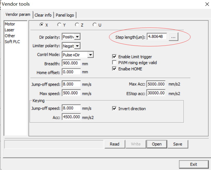
Back to your suggestion in regards to the motor settings of X-axis in the control system, could you be so kind as to walk me through it ? I really don’t know a thing about this, and I guess that doing blind modifications would lead to catastrophic results…
The screenshot I gave you is the manufacturer setting in Rdworks, which is about the setting of motor drive. Many users have lines that are unstable, or farther than they need to be. It can be improved here
Yes now it is almost perfect ; i’ve designed an adapter plate to be cut in 3mm plywood so that the Neje Module isn’t so down anymore. The workplane has been raised and I simply use the module’s integrated vertical slide to set my focal length
Please note that you cannot cut the mounting plate adapter much thicker than 3mm, as the screws won’t get through enough for you to tighten the nuts. You may use 3mm MDF or 3mm Plywood.
Other things you might want to check, if you didn’t already :
ensure your belts are properly tightened,
and most importantly that the eccentric nuts are set so that you don’t have any play anywhere.
Lastly, the speed and power are set for a single pass on the Neje A40640, for 3mm Birch Plywood. You might have to adjust according to your current laser module, material etc.


 ) just complicates the problem.