Hi,
Has anyone here had any experience installing an autofocus kit?
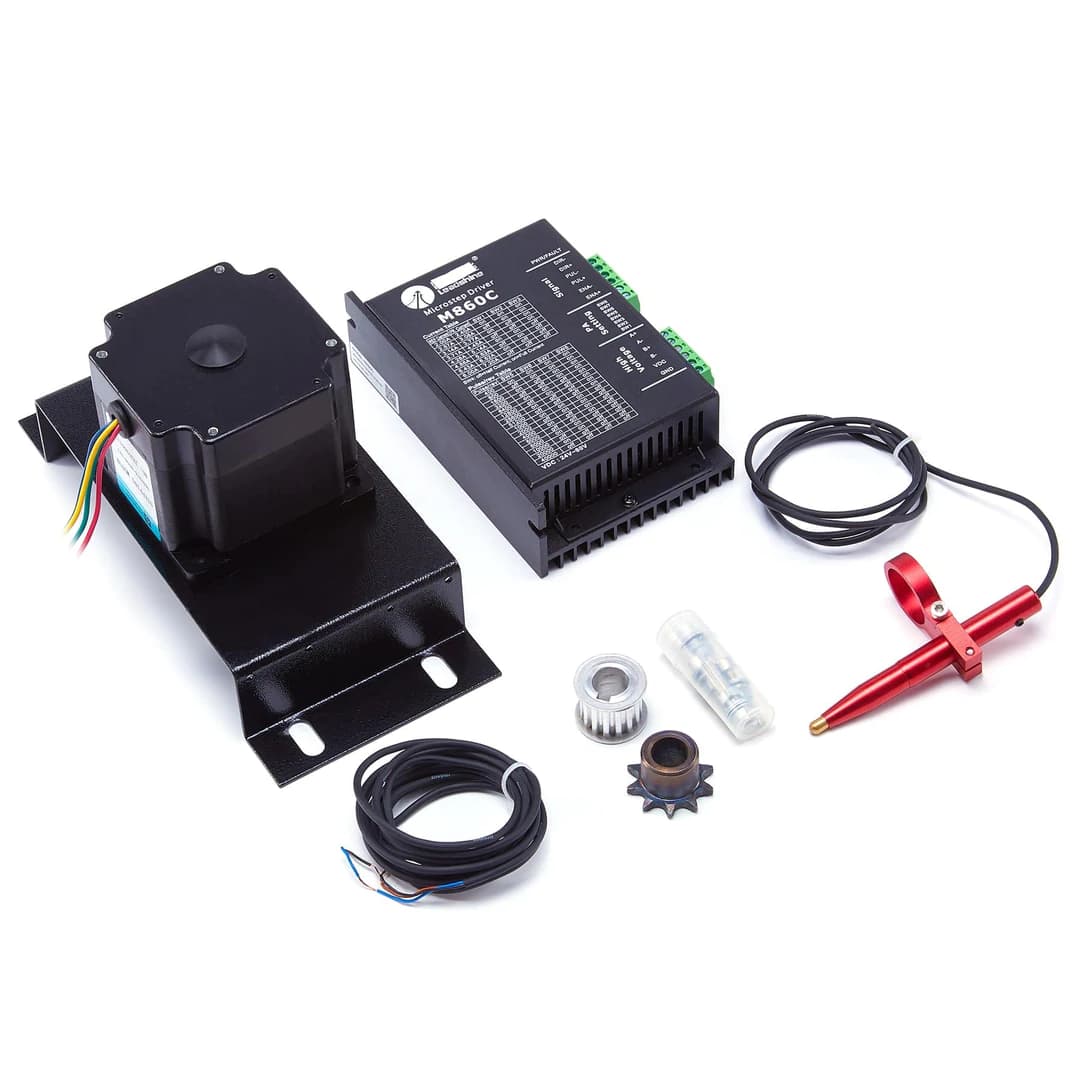
I have a red and black Chinese laser that came without autofocus and I subsequently ordered the autofocus kit.
The issue is that the belt is too tight to stretch into the mount and reach back to and around the belt attachment.
So I’m assuming that if I actually want to install this thing, I’ll have to replace the belt which looks like it would require me to disassemble the poles that move the table up and down to get the belt around them?
Unless someone knows of an alternate motor or motor mount that might allow me to install a z-axis motor on the machine without completely removing the belt?
Hi, thanks.
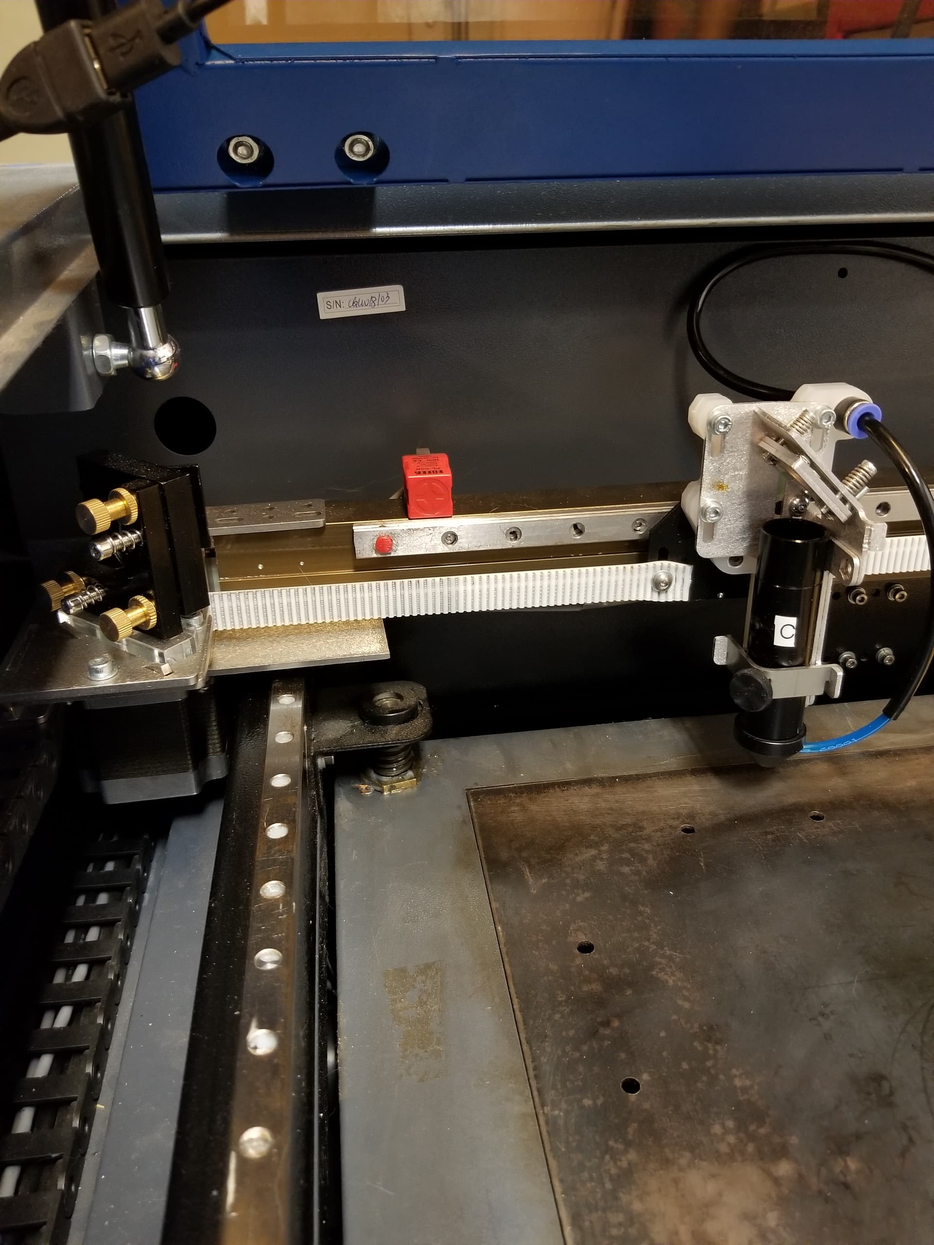
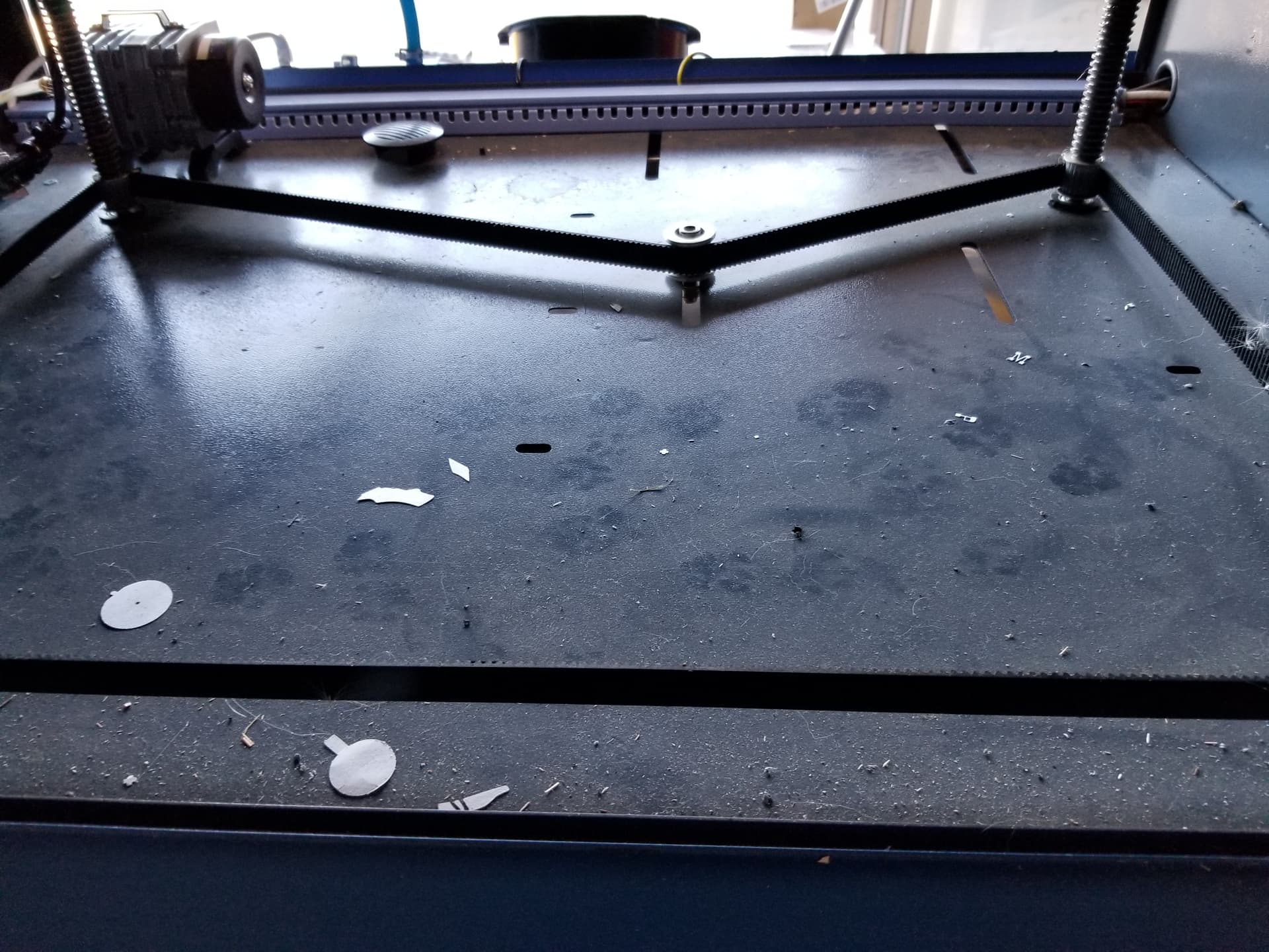
Yes, mine’s set up similarly. It’s a bit hard to get a good photo because of the amount of space I have behind the machine but here’s what it looks like (needs another vacuum:)
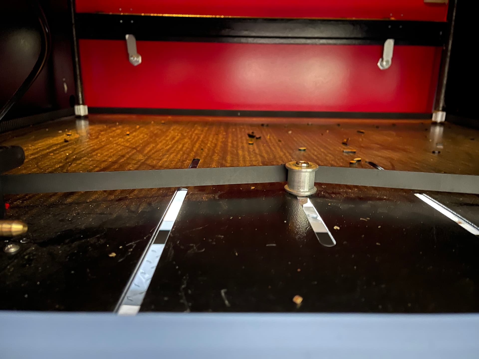
It’s intended to install the motor and mount inside the machine with the belt attachment coming down from the motor. The issue is that my belt does not have enough slack to reach back inside the mount to the belt attachment:
And now that the belt attachment’s on the motor it’s hard to remove plus trying to install it with the mount bolted from the bottom and the belt coming up through one of the holes in the machine floor would not work the belt holder is too far inside the mount (and the motor’s heavy).
I contacted OMTech and their response was “if you need a larger belt can we kindly ask for you to look for that for yourself.”
I’ve watched a video with a similar motor and mount but it seems that their belt had more slack than mine does. But if I need to replace the belt, I’m not sure where to get a good one.
Thanks
Or it’s possible that I am just an idiot and have been going about this totally wrong based on a video I watched:( I’m changing the alignment of the mount and voila I think it’s going to work. After that, back to readjusting my horrible laser alignment:(
Yeah, changing the orientation of the mount allowed me to get the belt on there. But the result was that I could only bolt it in two spots on the floor of my machine. There are no other places to mount it to another side of the machine. But it seems to be fastened tightly enough and I think it will work. Now onto wiring it.
Thanks. Can’t say the video was exactly “misleading” so don’t want to post. It was a different mount, different machine, slightly different motor – but it’s the only one I could find.
Anyway, I installed the motor, Have yet to see if its working. I just installed the autofocus pen but find that it slams into the mounts for the poles in the corners that raise the z axis up and down if I move the laser head to the far corner of the machine. This won’t happen if I’m cutting or engraving, of course, but it will be something I’ll have to be careful of when I’m trying to realign my mirrors. Any way to limit the x and x axis in controller settings so it will stop at the corners of where it will actually engrave? My laser size is 20 x 28 but the actual bed size is larger.
Also, I’m as of yet having trouble with my z axis. I’ll need to take a look whether I wired it correctly-- I’m pretty sure I did – but manual control with the controller doesn’t raise the z axis. I hit the z/u button then z axis and enter but I do not get the options that should be there.
Anyway – frustration!
Thanks for your help – again.
Cheryl
I’ve successfully wired the z-axis motor and confirmed that it’s moving. However, my alternate orientation of the mounting plate will not work because the “teeth” on the belt need to be contacting the belt connector and the belt connectors at the four corners. To get it set up like that turning the mount won’t work. So I’m back to needing either an alternate mount or getting a longer belt as the belt won’t stretch enough to fit to the center of the mount.
This is the video I watched:
Not misleading at all, but he has a smaller motor mount than the wide one provided with my kit and he seems to have more slack on his belt than I do. I was hoping to get this done today but I’m not sure where I can find something locally that will help me mount this motor differently.
Cheryl
If you make mounting holes, you will probably have to make ‘slots’ so you can adjust the belt tension.
Part of these machines being low cost is they are not what we call ‘standard’ and they vary for each manufacturer based on the Chinese Government ‘design’ that they are allowed to use.
Not easy to follow your description of the teeth not meshing. I’m assuming the ‘teeth’ on the motor end up on the wrong side of the belt?
I don’t know if you’ve seen any of the Russ Sadler videos on lasers. He’s a retired engineer and has made around 200+ videos. Here’s one he did on how the autofocus works with the Ruida controller and the issues he ran into… Might see if it helps…
Thanks! I had seen part of the video and saved it for later when I get to adjusting the autofocus pen. I have the pen installed but my issue has been the z-axis motor. I have it wired to the electrical now and the controller is recognizing it. Not sure how it’s supposed to sound or move but it seems to move the belt connector in small increments at a time vs a smooth continuous movement.
I’m playing around today with 3D printing a different motor mount – we’ll see if it works. There are slots in the laser floor and the mount I have is wide and corresponds to the placement of the slots if I turn it the way I assume it’s intended to go. But then the belt will not reach back to the belt connector.
If I turn the mount 90 degrees I can get the belt on the connector but only with the smooth side of the belt against the connector, which does nothing to actually move the table up and down. There’s not enough room for me to move the mount to a position where I can, with the mount turned that way, get the “teeth” side of the belt to be facing the belt connector.
So I’ve found a 3D print NEMA 34 stepper mount file, adjusted it a bit and am printing it. It has openings in the side to accommodate the belt. We’ll see if it fits and if it’s strong enough. But if it looks like it will work it might mean drilling some holes in the machine floor. Perhaps I should just get a longer belt, but I dread trying to take out the posts or the table or whatever I’d need to take out to get a new belt in there
Thanks
Well, I’m happy to say I got the z-axis actually moving! I rethought how I was installing them motor and figured out an different place to install.
However, now I’m not sure what the correct settings are.
The manual that came with the autofocus pen and motor just says to go into RDWorks and set the step length to 0.40000 so I chose that setting in Lightburn.
This adjusts the table a very minute amount – which may be what I want but I upped that to test.
With an increased setting the table moves smoothly up and down but only within a small range – that is, it seems it would just keep going up if I allowed it to, right into the laser head, but it won’t go down very far.
So far I’ve not been able to figure out where I can configure the lower and upper range for the bed. It seems there should be a setting for this somewhere. Nothing physical seems to be preventing the table from lowering more. I’m sure it’s a setting that I’m missing somewhere.
Cheryl
The numbers are critical if you wish the table to be moved the proper amount.
You could compute it, but I’m sure there are documents out there.
I have dealt with MW laser and he has good videos. Wish he did more with Lightburn, but I understand the issue.
Do you have limit switches? Or is the ‘probe’ the limit ‘zero’ switch?
Some setup a upper limit (usually at the bottom) that triggers LmtZ+, which is a hard limit and has to be enabled in the controller… I’ve see this but have no personal experience with it.
If that Z axes works like the X & Y, maybe there is a setting for continuous or ‘step’, like you can do with the other axes.
I see these hooked up to everything, so I have no idea how Z might be handled differently than the U axes as far as control both via software and the hmi.
I have nothing on either the Z or U axes at the moment. I have the hardware for the rotrary to move to the U axes, but haven’t done it yet.
I was really into doing this, but I notice that the table actually moved a few mm, mainly because the ‘screws’ it’s mounted on are not straight, making it rather useless for acurate step up or down without sifting the X, Y location…
Hi, Stil working on it. I calibrated the z axis and the table is now moving up and down smoothly and I’m able to use the autofocus pen.
But I’m having issues with my X and Y axis. I agree that the MW Laser video is very good – it just didn’t match my motor setup. At one point he says to reset the X and Y axis which I decided to go ahead and do as I was having issues anyway – and the laser head ran into the corner at the far back left of the machine!
So now I’m trying to figure out how to set the X and Y axis of the machine so it stays in the cuttable area of the machine and does not run the laser head nor the frame for the autofocus pen into the machine corners!
But I’ve made much progress and I’m almost there!
Cheryl
Thanks.
Since I tried the XY axis reset the X axis will not move unless I turn the machine off and move it manually. The only thing I can think of is that I somehow disrupted the limit switch on the left side of the machine. The laser head runs into the left side of the machine and doesn’t stop until I press escape. I see a Y axis limit switch that is lighting up. I see a similar switch around the right side of the laser head. According to the laser manual there is supposed to be an x axis limit switch. But the photo is small, black and white and doesn’t really show anything. I don’t see anything there that looks like the Y axis limit switch, nor did anything fall off the machine. I rechecked my wiring and don’t see anything loose in the areas that I messed with to install the z axis motor.
Frustration!
Cheryl
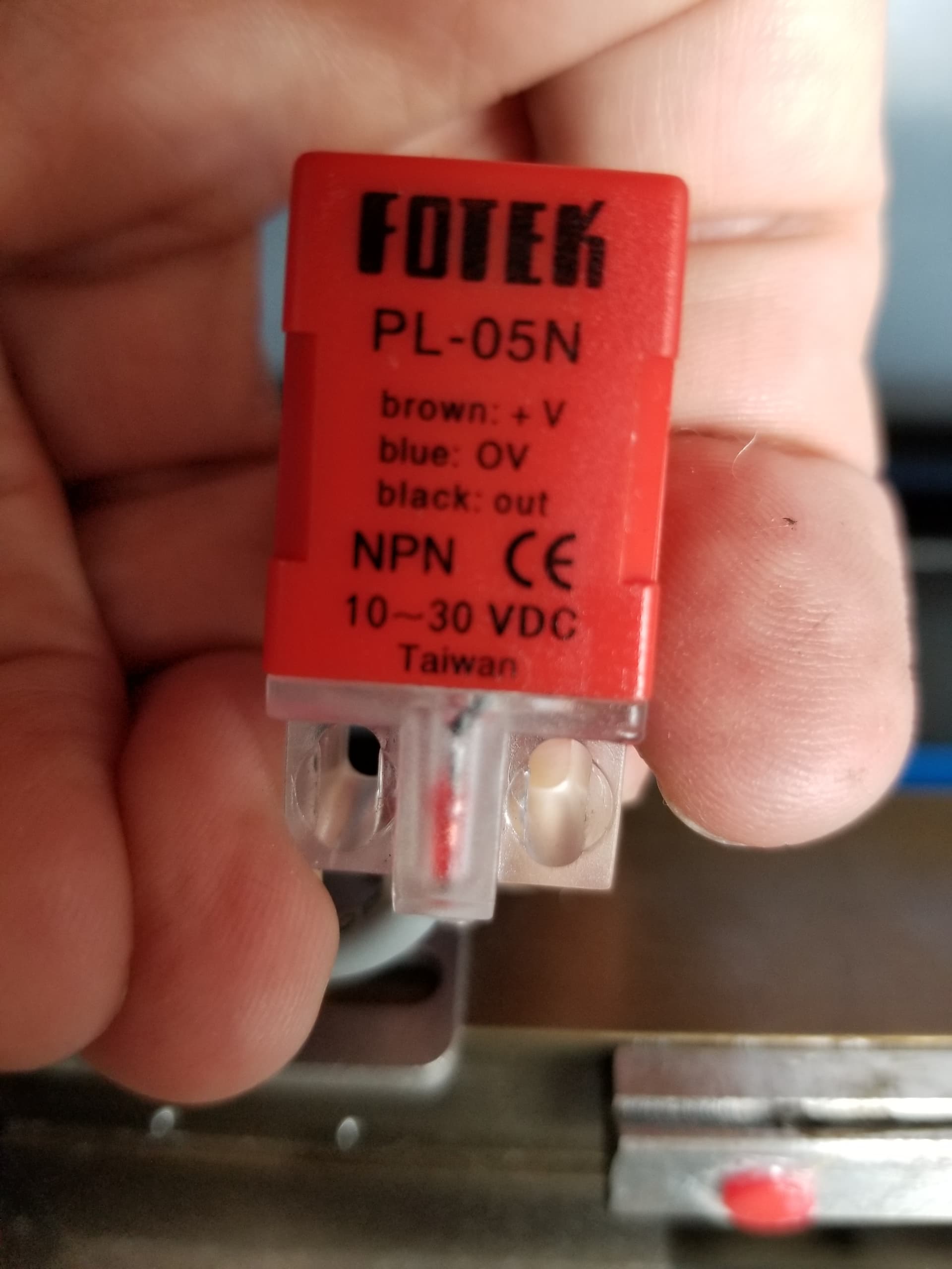
Touching the sensor with a metal object should show on your console. If it lights up on the device, but not on the console, then a wiring issue is suspect.
There is also an ‘led’ on the controller itself that will illuminate when active.
If all the diagnostics work OK, the target is not passing close enough to the sensor.
Mine ‘homes’ to the rear/left and you can see the orange sensor there that detects the head ‘home’ or limit switch. I had to move it when I changed the head.
Yeah, I see two of them – the one for the Y axis is at the back right of the machine. There’s another one near the laser head to the right. I don’t remember one ever being on the left of the machine ,though the manual says there’s one located there.
I had looked at diagnostics and I only saw Y activated.
I am betting that the power for the X axis trigger was the brown cord which had to share space with the power for the Z axis motor when I connected it and that it’s somehow not connected completely though I can’t see that looking at it.
Anyway, it will be the next thing I check. I’ll likely need to get back to it tomorrow, though as my laser shares my husband’s “man cave” and office space and I try to limit my time fiddling around with the laser to times when he’s not home. He’s willing to help and helped me hook up a better power situation in our garage so I could power the laser and all the peripherals but, for various reasons I will not mention here, I don’t want him actually messing around with the laser:(
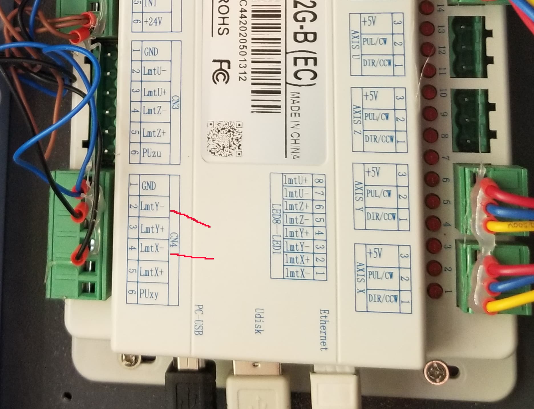
Do you know where the X axis limit trigger generally gets wired on these machines?
Hi, Turns out the power is OK. On my machine the limit switches are both on the right, though my machine manual indicates one to be at the left.
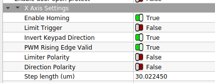
Though I’m using Lightburn mostly, I found someone’s RDWorks file for a different machine in another post and used that to reset my controller so it was again allowing me to move both the X and Z axis. I then reversed polarity on the X axis. This somehow allowed the X axis limit trigger on the R to work and has stopped it from slamming into the machine on the left.
However, previous to all this when I hit the right controller button it would go right and now it’s the opposite – something to get used to and I’m concerned about how this will affect cutting and engraving but haven’t been able to test it yet.
I’ve decided to take this opportunity to tackle where my origin is. My bed is 700mm x 500mm. I’ve had the origin, and do again, at the back right of the machine. So far, I haven’t tried cutting anything big at the machine limits. But it seems to me that that back origin is a couple inches away from the back of the bed which wouldn’t allow for an actual cutting or engraving area of 500mm.
Is there any way to move the origin back on the y axis a bit more? RIght now it’s perhaps 2" away from the back of the honeycomb bed which when I come to wanting to cut an item that takes up the full space doesn’t actually allow a full 500, nor even 490.
But now that I’ve reset, the laser head does not want to move back more and if I let it it will bump into the front right corner of the machine.
Perhaps I should take this to a separate post as it’s no longer anything to do with the Z -axis motor or the autofocus pen, both of which are working as intended.
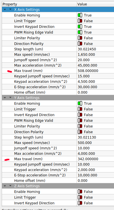
I assume you changed ‘Directional Polarity’. You might flip the ‘Invert Keypad Direction’ and see if that helps…
With power off, you can manually move the head anywhere it can go. That will tell you the area of operation.
I have a lightweight head on mine. The head has the ability to go much further than the ‘work area’ one issue is that the screw jacks for the z axes become obstructions. My area increased from 500x300 to 504x344 or something near that. But your machine should allow you to navigate the complete work area.
If you have an offset set, that can limit it also…
You can start a new thread if you wish. Make sure you point out what you did to solve the issue. It’s rough to find the problem you’re trying to solve and at the end it say ‘thanks’ with little clue of what they did that solved it…


 This won’t happen if I’m cutting or engraving, of course, but it will be something I’ll have to be careful of when I’m trying to realign my mirrors. Any way to limit the x and x axis in controller settings so it will stop at the corners of where it will actually engrave? My laser size is 20 x 28 but the actual bed size is larger.
")