We recently just got our OMTech 150W installed and started in on some test cutting.
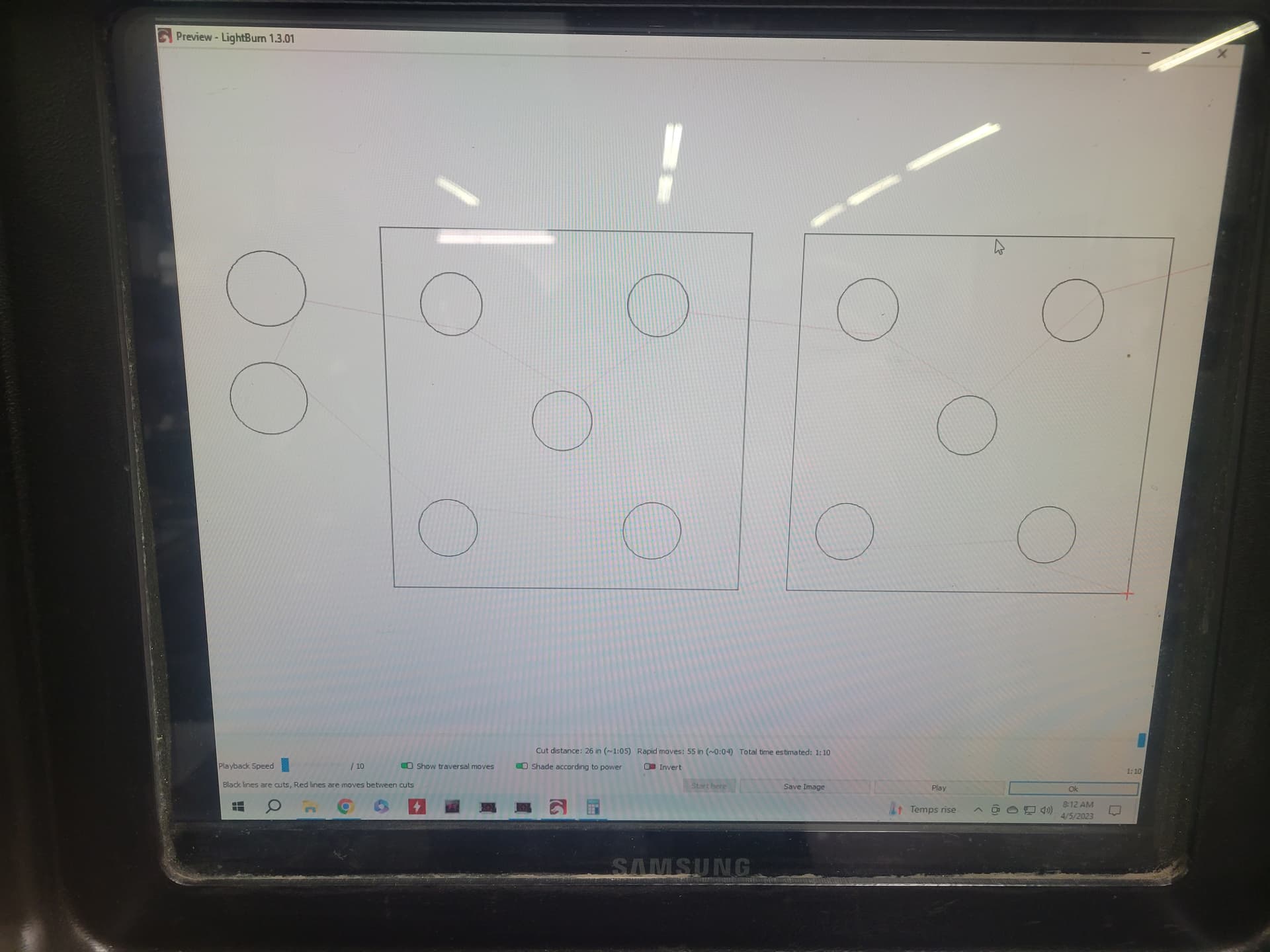
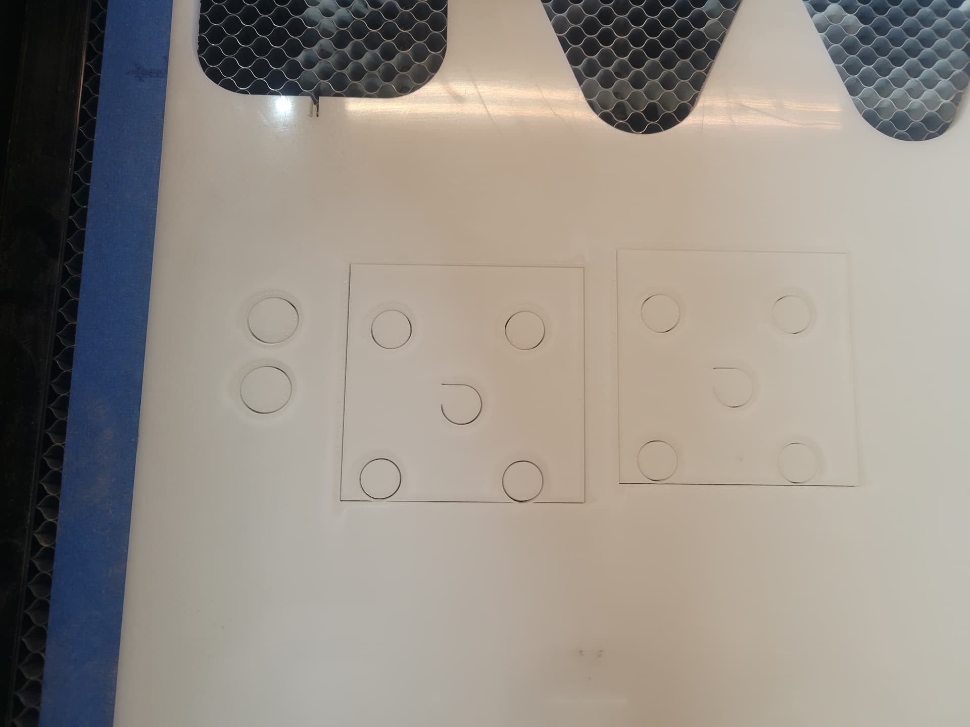
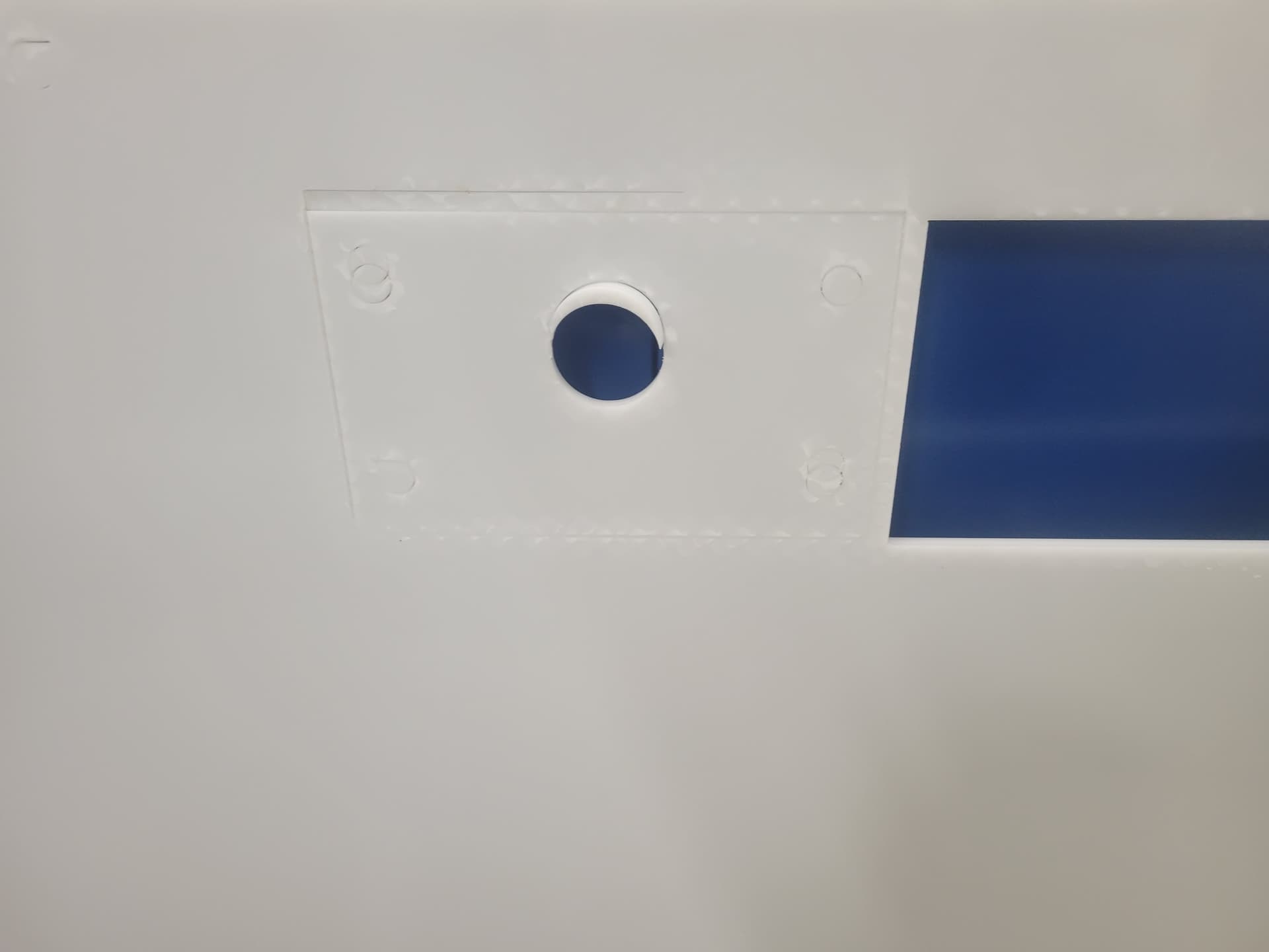
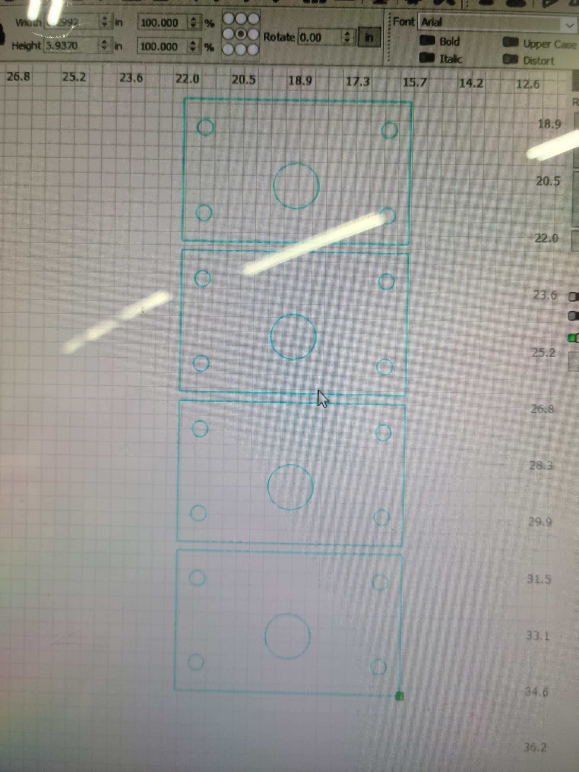
We have had just frustrations with trying to get these holes cut properly. For some reason, our preview looks fine and all, but when we go to cut that first hole out, the machine does a small line then begins the circle and does not complete it.
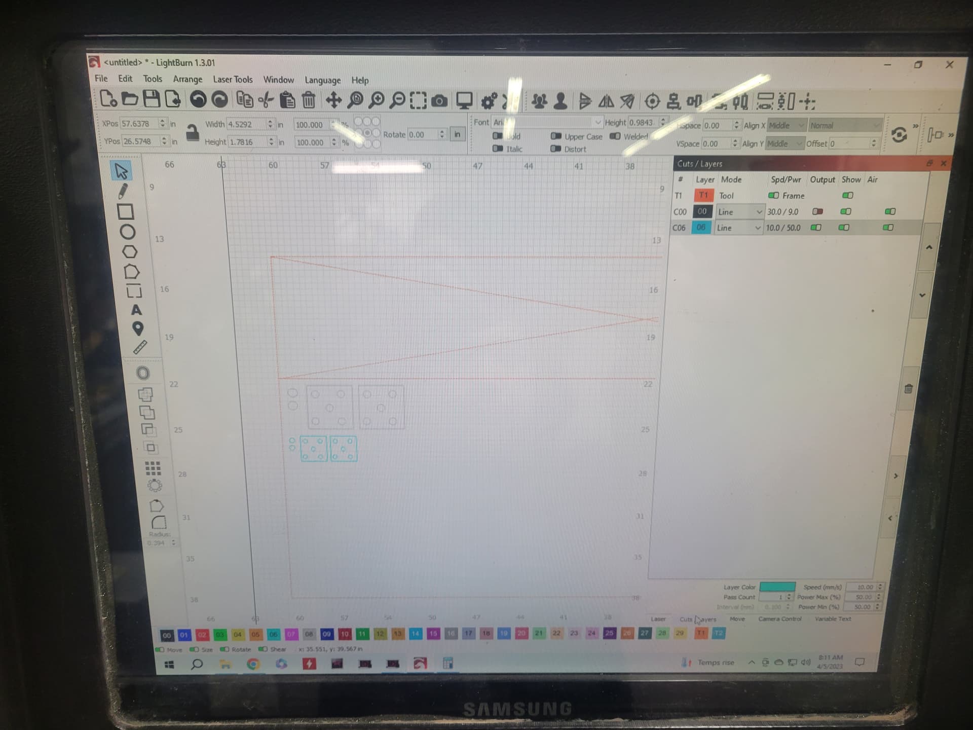
We triple checked out settings and this shouldn’t be happening. We have also noticed that when we begin the cut from our picked origin, the machine returns to a point slightly above the started point.
I think your shiny new machine has a bad case of mechanical backlash in the Y axis: something is loose between the motor and the laser head.
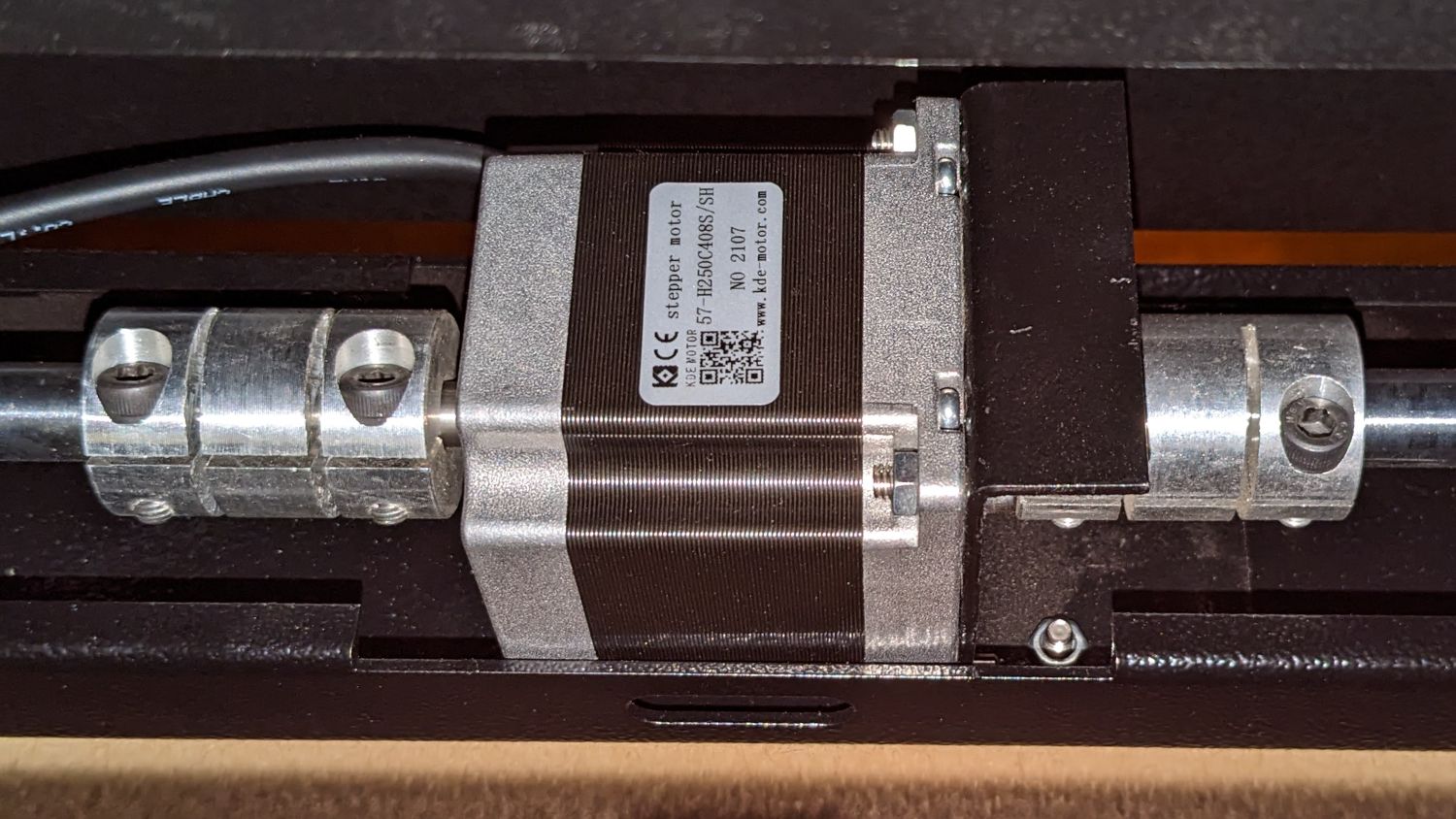
I have the smaller 60 W version of that laser. The Y axis motor is in the back of the cabinet where it’s visible, if barely reachable, through the rear passthrough hatch.
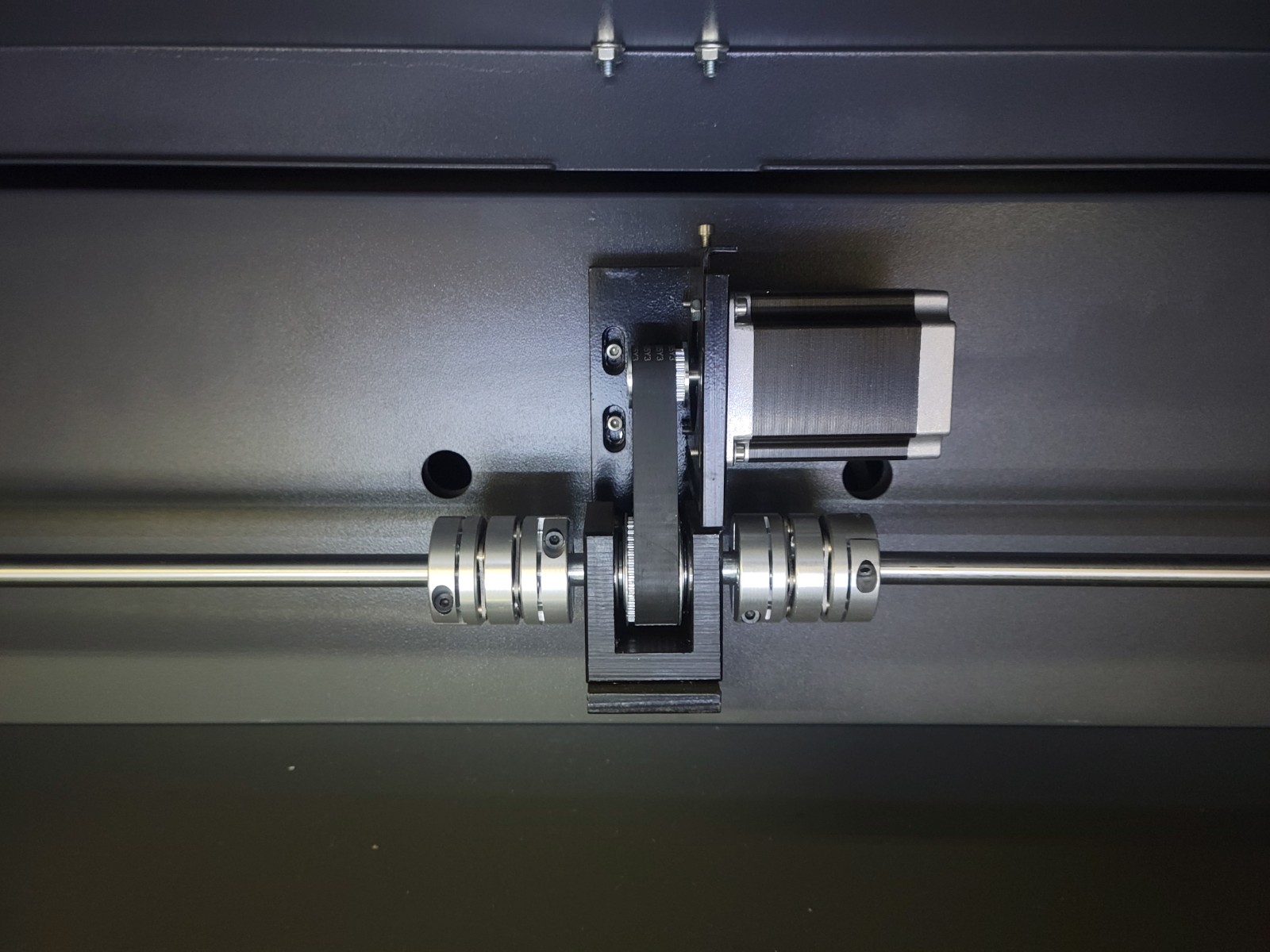
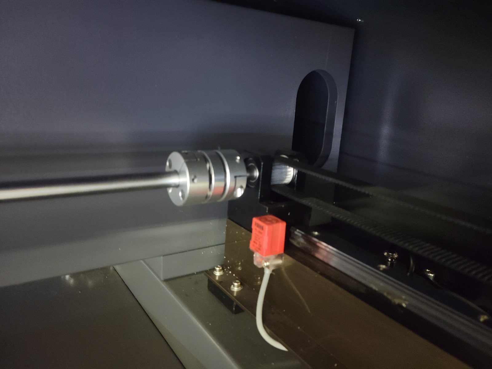
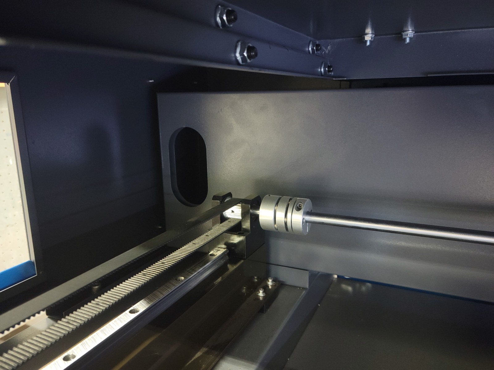
The motor has two shafts and each shaft has a flexible coupling joining it to the long shafts to the pulleys on either side driving the Y axis belts:
Wow! Not only can you see both ends of those shafts, you can actually touch them. Much better than what I have!
It looks like the belt pulleys have setscrews buried in the teeth, so I’d expect the motor pulley and perhaps the one it drives do, as well. If you haven’t wriggled your way in there, do so and check 'em out.
A setscrew may feel snug, because it’s jammed at one side of its shaft flat, so loosening it, rotating the pulley back and forth, then snugging it down again will recenter it.
In addition, make sure all those pillow / bearing blocks are firmly screwed down and cannot move.
Another place to look is at the laser head itself, which should be firmly screwed to the X axis carrier.
Folks have even found loose mirrors and lenses and even the laser tube itself, so it’s worth poking at all of those to make sure they’re tight.
The belts should be snug: not guitar-string tight and not sloppy loose.
Basically, make sure there is absolutely no looseness anywhere. Don’t go gorilla on it, but anything that feels loose with a firm shake is loose.
No and no, respectively.
The key point is that the head must trace exactly the same path every time. If it doesn’t, then it’s a mechanical problem.
After you have carefully verified all the screws and other bits, then there are a few configuration settings to review, but those are rarely a problem on big machines and never the place to start.
In post 3, the belt drive can introduce backlash also…
I think it’s losing steps as a first thought… picture 2 of your initial post there a loss of position. The circles on each are not in the same place. It’s evident from the circle on one touching the outline, not on the right one.
does the machine return to the proper place after the run?
a. assume it home properly.
b. assume you have it set to return somewhere.
stepper motors set for an incompatible step rate or step/rotation value, can cause issues
The flat quarter-arc of those circles show that the Y axis is not moving at all, while the offset squares show the Y axis moves just fine, but offset by the same amount the whole time.
You can also get the thing to fail pretty much on command, which is incredibly valuable.
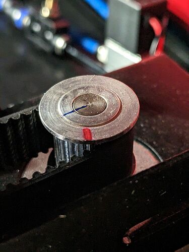
Now that you’re comfortable with crawling around inside the cabinet, do it again with a Sharpie. The task is to mark every place where a shaft meets a pulley or coupler:
The blue line crosses the joint between the motor shaft and the pulley, so that if there’s any rotation it will be immediately obvious.
As @jkwilborn points out, the parts near Y axis motor are prime suspects, because if either of those pulleys slips, the error appears on both shafts. Marking the shaft at motor’s driven pulley between the arms of that pillow block looks tricky, but I’d put some money on that one having a screw loose.
It also looks tough to mark the pulley-to-shaft joint at the ends of those long shafts.
You must mark every possible joint, because the one you don’t mark will be the one with backlash.
Now, here’s the gotcha. The backlash has two stable states and you’ve marked only one of them. The axis can switch to the other state, run for a while, then switch back again, whereupon all the joints will look perfectly innocent (and probably smug) when you check.
You probably can’t catch the problem while it’s doing one of the circles, but while it’s cutting an off-position rectangle slap the Emergency Off button to freeze the machine in its tracks.
Then pop the hatches and go hunting!
You may have to do that a few times if the odds are not in your favor, but that’s the general idea: run it until it fails, freeze it, then examine the evidence.