Hello,
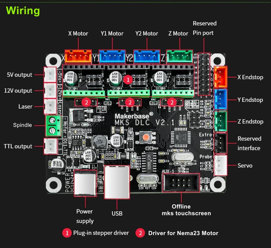
I am upgrading my 80w machine to a GRBL motherboard, and seem to ran into a issue. I can’t seem to find how I am supposed to hookup my laser to the board. I have seen that you need to “potentially” put to the ttl output, as referenced in the above image, but when I do that the laser tube continues to fire and doesn’t shutoff. does anyone know where I am to properly hook my laser up to. I have also tried to the laser output and that seems to have broke my power supply (now the laser continuously fires when I turn the machine on)
Thanks In Advance,
ZIM
I think you have to connect only gnd to the input of tube PSU, but let’s wait someone more skilled than me 
ok i connected my from the TTL output connection the S goes to the where the potentiometer is connected on the power supply so you have to remove the wire . so on my power supply the potentiometer connection is label (G) (IN) and (5V) so i unplug the (IN) wire connection only and replace it with the S wire coming from the dlc motherboard. and the G you need to connected the connection that triggers the laser on mine is label (L).
You have two solutions to do this and I will tell you exactly what to do to solve your problem, first tell me what your PSU model is?
I follow this, is intresting
Hello,
I will update this with a picture of it as soon as I get home from work, it is a 80w power supply (brand= vevor) a black one.
Hope that helps,
Zim
Link to where I bought it from
(Laser Power Supply Co2 Laser Engraver 80w Laser Power Engraving Suppli – Vevor US)
I know very well what grbl does, but I have not worked closely with the blc board you are using.
Are the laser settings set on this board by default?
If not, you need to make some changes.
Did you do the wiring like the picture below?
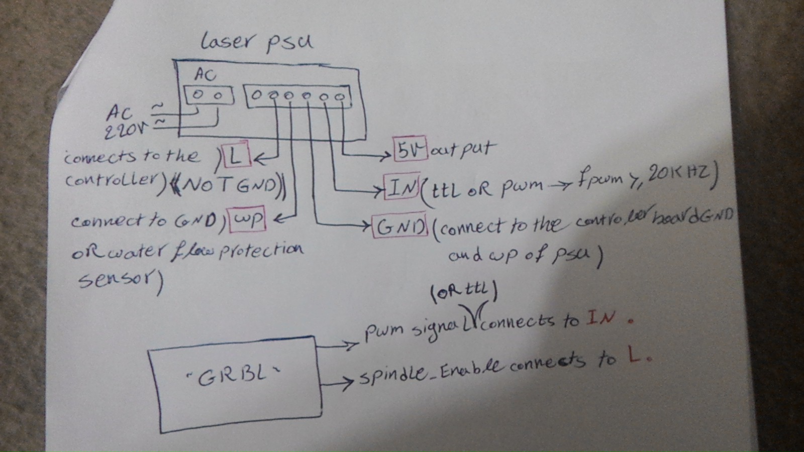
by the link that you provided it seems like that power supply can trigger on high and trigger on low so all you need to do is connect the S connection from dlc motherboard to the H on the power supply
the S pin provides 0 to 5v depending on the power % you specified on lihgtburn for example if you set 50% power the S pin will output 2.5v
I’ll double check my wiring this weekend (getting new power supply on Saturday ) what is the s in this case on the dlc board?
is the pin label S on the TTL output connection
if you look at your dlc board there is a 2 pin connection one pin is label S and the other one is label G so you only use one wire to the S pin
Julio,
Thank you for the reply I am getting my new power supply today, as soon as i get it I will hook it up and see how it goes with what you recommended. Ill keep yall posted.
Regards,
Zim
Julio,
I tried to install the wires the way you said to and it didn’t appear to work properly. The laser stayed always on when I powered the machine.
Regards,
Zim
you connected S pin to the H and with no other wire connected to the G is that correct .
now is the laser turns on as soon as you power up the machine or when you run a file.
so my laser is wired from the DLC ttl connection S pin to the IN connection on the power supply and the G pin to the L connection my power supply doesn’t have H connections
the key here is not to ground the laser because that will trigger the laser on. you can try removing all the connections and start connecting one at a time to see whats triggering the laser
on a side note when I power on the machine my laser does turn on for a second or two then it turns off to fix that i install a mosfet relay to disconnect the ground between G and L connection I use the A3 pin on the DLC to activated the mosfet and allow the ground to pass thru when LIGHTBURN activate the air assist
Good Morning Julio,
I didn’t have anything else connected to the laser, but this coming weekend I’ll take a look at my wiring and do that (connect one thing at a time). The laser stayed on as long as I had the H wire connected to the S connection. I did do it fairly quickly yesterday, so maybe taking a second look at it today might perhaps show that I might have plugged the wrong wire to it. (have two wires coming out might have put GND there making it stay on). Ill take a look when I get home and post an update on it today. Also could you link to the mosfet you used, I would like to add that to my machine due to having the water pumps turn on with the the computer, but the lasers psu turns on when I turn the power on.
Regards,
Zim
this mosfet relay i use to prevent ground to the L terminal connection 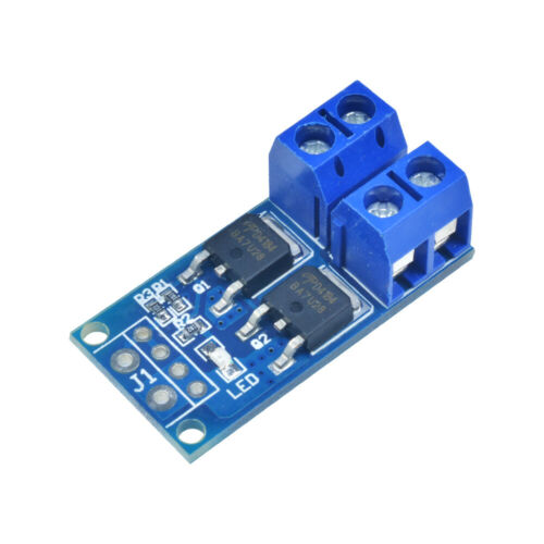
and this solid state relay is to turn water and air 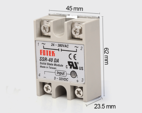
also try to connect the laser to trigger on LOW
the S connection to the IN terminal on the power supply an the the G connection to the L terminal. this is the way i have mine connected
Julio,
Thank you very much for the pictures and the new information. I will be looking into this more tomorrow, I am waiting for my new electronics plate to be sent to me (custom plasma cut plate for my electronics box). If it’s not here by tomorrow I will still try to hook up the new way you recommended and see if that is the right way. I will also look into the relay situation more I have din rail relays so I may add one more for the lasers gnd and do as you said have it enable after hitting start. The only thing that kinda sucks too is I have some custom plates made for my y axis (rod holders for my sync belts and axis plates) so I can’t really try cutting anything yet until they get here as well, but I can try hitting start and see if it works at least. Fingers crossed that everything works.
Regards,
Zim
While I wait for some parts to get here I do have another question regarding using dual endstops for my y axis to auto correct the homing process. If you want I can make another post for this but I thought to perhaps do I through this one. Is that something that is doable on this motherboard if so how could that be done?
Regards,
Zim
Update
I got the motherboard wired up to how you said and it worked. There are some minor issues though. I had a potentiometer on the machine for pwm but now it isn’t hooked up due to the way it is wired now, and when I get it to fire it I very weak. Could I wire the potentiometer back up inline to it? Also the other minor concern I have is that my test fire button stopped working in wiring the machine this way. Do you potentially know a way to get that back up?
Regards,
Zim
if you want to use the pontiometer you have to invert your PWM from positive to negative with a NPN transistor and 100 to 300 ohm resistor
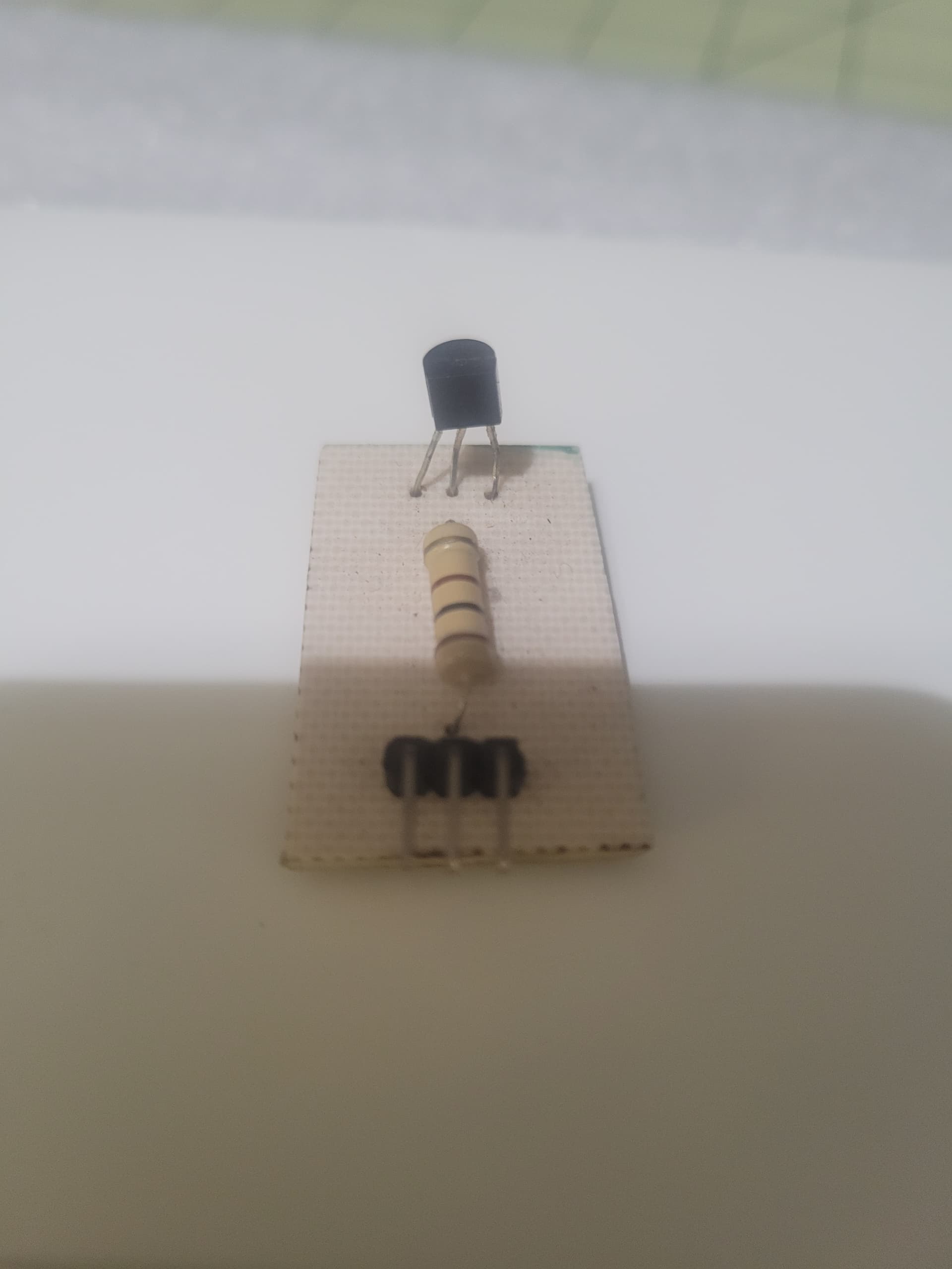
i tried it and it worked but i removed it because i was getting a hizzing sound when the laser was on
i am not clear on why you need two endstop on y