How to create sketch for a dial?

Is it possible in Lightburn to create an array or object in a circle like in the image?

Now that I type this, I suppose I could do it with a rotary pointed up toward the laser

But is there a way to create an array and curve it into a circle like you can with text?

Try something like this. This assumes you have lines of 3 different lengths like in the example:

  1. Create a center circle shape. This will only be used as a reference.
  2. Create one of the longest lines above the circle
  3. Select line, then add center circle to selection. Use the Circular Array tool and set the number of longest lines that you want.
  4. Repeat for second longest line
  5. Repeat for shortest line
  6. Repeat for numbers. Edit number as appropriate after rotation
2 Likes

Wow, that worked great! Thank you so much!

Maybe I will attempt the stuff in the inner circle. I learn more on this forum


2 Likes

Wow. Nice.

I’m having trouble with resizing the lines aren’t directly on an axis (0,90,180,270 degrees)

If I try to make the #1 line “taller” with resize it will also make it wider.

Did you do two sets of lines, or one, and resize the longer ones?

2 general approaches:

  1. Grab the side handles rather than the corner rectangles if resizing directly. If you hold CTRL while doing so it will resize from the center of the shape.
  2. Use the Numeric Edits toolbar to adjust width or height. Use the 9-dot selection in Numeric Edits toolbar to determine position from which the resize will occur.
2 Likes

I haven’t figured out how to size the ones on an angle.
I did mine with the copy along path. I couldn’t figure out how to do it with array.

1 Like

I think I misunderstood the problem with the #1 line. I understand that to the be first line which I assumed was top. After reading @Dskall’s comment I’m reconsidering that #1 refers to the line associated with the 1 mark.

While possible to scale along one dimension of the rotated shape it’s not particularly straightforward unless the shape is still a rectangle primitive. If so, use width in Shape Properties window to adjust the size. However, those values can often get out of sync with the actual shape size under certain situations. It’s likely faster/easier to recreate the shape.

Here is another strategy for making things easy to align and allow for experimentation:

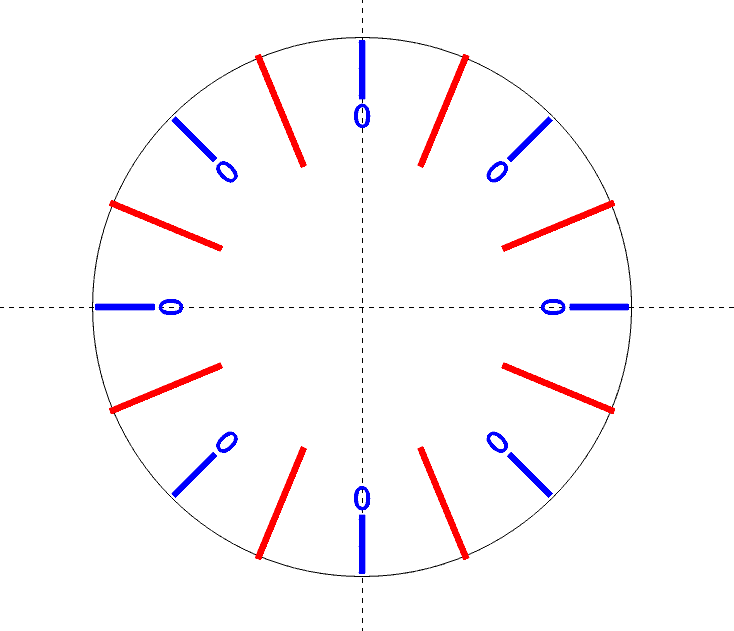
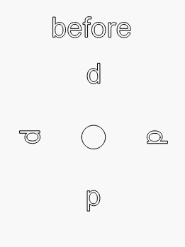
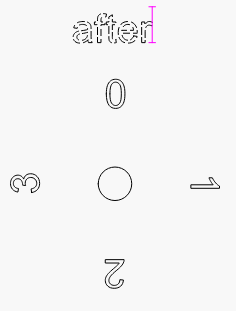
  1. Create all 3 marker styles at the 12 o’clock position. Align, size, and position them as you would like them to appear.
  2. Create the circular array for every line position with the short line
  3. Create the circular array for every desired position for the medium line
  4. Create the circular array for every desired position for the long line
  5. Select all shapes, then weld them so that overlapping shapes merge together.
2 Likes

This method works… I just created separate arrays and deleted the lines I don’t need/want.

1 Like

Now trying to figure out the auto increment feature.

I dont think you can auto-increment on the same part.

Set text type to Serial. For the text area itself, use d or dd. Set Auto-increment to 1. Test the effect in Variable Text window.

I was wondering about this in circular array. Incrementing the numbers in the array?
image

Yeah, doesn’t work that way. Like if you tried to make a ruler with the array tool, it wont increment numbers.

The increment numbers is if you wanted to make a bunch of parts and put unique serial numbers on them, or read names out of a file for ID badges.

Well, it should. lol

1 Like

Did you follow my instructions? It works as advertised.

image

image

1 Like

Searching the forum can provide additional information on this subject. One in particular:

Wow! That’s great!!

I can’t thank you enough for all of the tips!

1 Like

Nice. Is there a font for the zero’s?