How to set up the SKR 1.3/1.4 Board with the K40 Laser

Hello everybody,
I successfully set up an SKR 1.3 board to operate my K40 with Smoothieware running on it. Its been a while ago so this documentation may not be perfect.

The first thing you need to do is to get the latest version of smoothieware here.
Rename it to firmware.bin and upload that on your SKR board with either the USB cable or the SD-Card.

To control the laser with the SKR board we need to connect two inputs of the laser PSU to free pins on the SKR board: the laser enable and the laser pwm input.

(The laser enable pin can be attached to any free GPIO. The laser PWM pin can only be attached to PWM capable pins. On the SKR1.3 these are P2.0 - P2.5, P1.18, P1.20, P1.21, P1.23, P1.24, P1.26, P3.25 and P3.26. The microcontroller of the SKR1.3 only outputs 3.3V on the GPIOā€™s thats why we need a logic level shifter module like the one from Sparkfun. This is important only for laser enable. 3.3V turned out to be fine for the PWM Signal, so I did not level convert that signal.)

The following diagram shows how I connected everything. (I used images from Sparkfun and Duet3D forum user hector, so credits go out to them.)

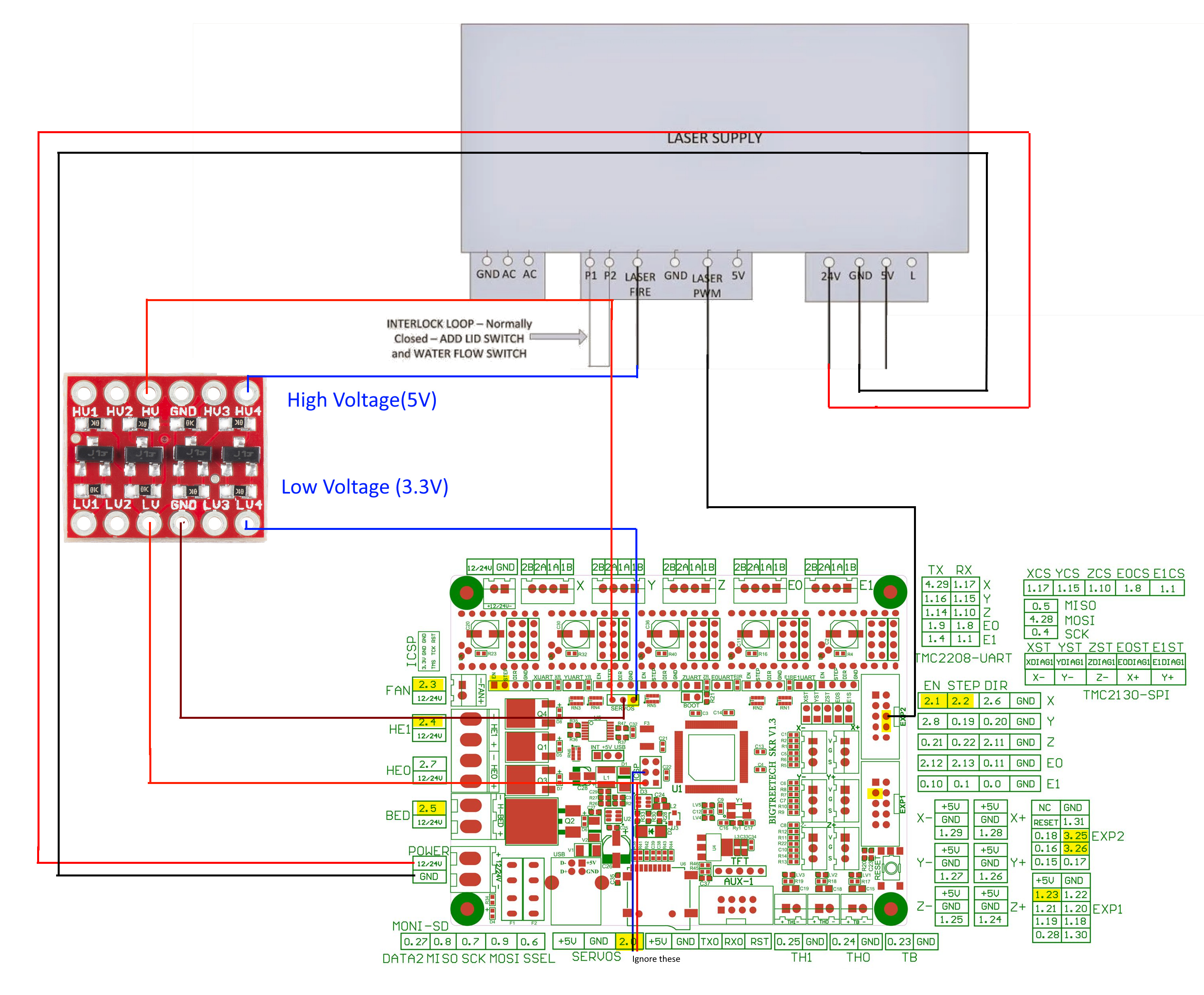
(Right-click -> view image to enlarge the picture)

I used Pin 3.25 as PWM pin and 2.0 as laser enable pin. My config file can be found here. Upload that to the SKR and reset it.

Now connect the motors. I donā€™t use endstops on my K40 because I broke the flat cable connecting them. If you want to use your endstops make sure to connect them on a free pin and assign them in the config according to the pinout provided. Also I donā€™t have my flat band cable anymore so I just use a regular stepper motor connecting cable. The motors can be plugged into the skr board without any modifcations.

If you have the flat cable DONT try to solder on the pins. This is how I destroyed mine. Use the middleman board (google it) instead.

When everything is connected the next thing we wanna do is set up the power levels for our laser. In config.txt there are a few parameters that should be adjusted to your laser. These are maximum_power, laser_module_minimum_power and laser_module_default_power.

In our terminal, we can set up the current power level with the command ā€œfire 10ā€ for example. This means that our PWM Signal has a 10% duty cycle and can be understood as percentage of the maximum power level (that destroys our K40 laser tubes so never use fire 100). The fire command doesnā€™t acually fire our laser, you still need to push your fire button to see what the command did.

Now, start with fire 10 and push your fire button to see if the laser fires. If it doesnā€™t send fire 20 to the SKR and try again. What you now need to test out is when you laser begins to burn something. Remember the ā€œfireā€-value then. Next carefully raise the power level to find the level, where your tube draws the maximum allowed current of 18 mA. I suggest to stop at 15 mA to give the tube some extra life. Remember that value as well.

Now you need to put these values in you config. If your laser started firing at fire 16 you set up the value of laser_module_minimum_power to 0.16. If your laser drew 15mA at fire 55 then set maximum_power to 0.55. The parameter laser_module_default_power is the power set up when you turn on the device and push the fire button without setting anything up.

When you set your power level in LightBurn it now assigns 1% power to 100% power between these set up boundaries.

Lastly you can burn some test lines and measure them to calibrate your steps in the config. Smoothieware describes x-axis as alpha, y-axis as beta and z-axis as gamma that may be a bit confusing when you see the config for the first time.

Thats it. Now you have a Smoothieware powered K40 controlled by a SKR board.

5 Likes

Good write-up.

You chose to leave the power dial out of the loop?

1 Like

Itā€™s not nessecary because the skr has an own power regulator, so Iā€™m using that, but you could connect the hv connection of the logic level converter to the psu dial as well.

Good write-up.

Very nice. Thanks for sharing.
I use SKR 1.3 as well for almost a year now. my configuration is completely different. i PWM and pull-down PSUā€™s ā€œLā€ pin using SKRā€™s fan fet directly as i just need to pull it down and thatā€™s exactly what the fan fet is doing (I leave the 24V pin out of the game - I am just using the [-] leg to pull ā€˜Lā€™ down). I kept the M2 control panel as it produces the variable TTL level i need for making sure Lightburnā€™s 100% is 15mA.

Works like a charm.

1 Like

Hello Squid,
the fact that you described using it started me to figure out how to do it. It sounds like your configuration is much simpler than mine. So if I got that right you are just connecting 5V instead of 24V to your SKR and then use pin 2.3 as PWM connection? Would you mind sharing your config file as well?

I assume that you then also connected either Pin 2.4, 2.7 or 2.5 to the ā€œLaser Fireā€ pin, right?
That is indeed much simpler and removes the need of the level converter and that 5 connections

Yes. pin 2.3 is for laser pwm. connected fan fet Drain only to psu pwm in. skr is powered by 24V, shared ground with psu. I left the M2 digital control panel to drive psuā€™s analog voltage input (same should go for analog pot). I am using pin 2.4 for external peripherals like air assist and fume extractor controlled by lightburnā€™s start/end Gcodes (driving an external 220VAC SSR for this). pin 2.5 = ttl pin which I use to turn on red led which shows me the tube is exited even if powered like 1% and no laser output. very handy. since lightburn added start/end gcode i donā€™t use this output anymore. no need.

1 Like

I was thinking to do the same thing but then, if you connected 24V to the SKR in, what voltage do you measure at the fan output? Isnā€™t that 24V then? I donā€™t get what you mean with the fan fet. Can you maybe give us a little sketch? :slight_smile:

1 Like

It goes like this:
The controller fetā€™s ports which drives for exp your heaters and fans are pwm outputs. each port has two terminals - one is fixed 12/24V (VBB) and the other is the drain leg of the mosfet. itā€™s not the VBB which is PWMā€™d but the flow to ground. if youā€™ll look at the attached schematics leg 1 of FAN output is Fetā€™s Drain to S (ground) so i just used this leg to pull-down my laser pwm port (which is pulled up by the psu to 5V ttl either internally or by a potentiometer - each psu is different). the laser output is inversely proportional to the voltage/frequency of the pwm. i hope this makes sense. I will see if i can find more drawings for you. whatever you try - be careful and keep safe.

Itā€™s not necessary, but good to have.

The dial controls the power outboard of the controller, so your software controls all power, but the dial can control within that predefined power setting.

I used it yesterday while engraving paper - even at 12% to was too high, so slowly turned the power down until I got no output, then back a fraction - nice clean lines, no cut-through.

Hi guys,

Iā€™m new to the forum and just got my K40. Iā€™m still tinkering the machine (mirror alignment) and wanted to change the board because I know it is not the best of controllers. I came across this discussion and ordered the skr 1.3 and 2208. I still need to ingest how to connect the skr to the laser. Iā€™m not good in coding but wanted to learn. If itā€™s not to much of a hassle, is it possible to share your config? I would really appreciate it.

Hello Ambut,

you can do it just as I described in my first post. It works but you need to buy the level converter as well, its about 2$ only. I can give you advise on that. You donā€™t need to learn anything about coding to understand what we were doing. Everything that is important is how you set up the config file (as described in the first post).

The possibility that I was discussing with Squid is to remove the need of the level converter. The K40 PSU uses a 5 volts PWM signal (google PWM) to control the powerlevel of the laser. The only difference in what we did is how we reach the 5V. You can use the level converter to convert 3.3V from a GPIO-pin on the SKR to 5V. Squid used another pin that works a little different from the one I used. If you donā€™t like to buy a level converter and you happen to have a potentiometer at home tell us and we can help you.

Else you can just buy a level converter and connect everything as described above and use my config file (its linked in the first post)

Hi Yassin, I appreciated your time and effort for your work and your response. I know a little of electrical but zero with coding. My plan is to use less additional components and wiring but since you already posted the diagram and config file I will give it a try. Still waiting for parts and hopefully once I get them everything will work as planned.

Again, thank you.

Hi Yassin, I have been using the SKR 1.4 turbo board with Marlin on my laser cutter for a while and have had many issues. I stumbled across this post and I am thinking about giving smoothieware a go to see if it is more reliable. I noticed that in the title you mentioned the skr 1.4 board. Is this because the two boards have the same pinout and the config file would be identical? Another question I have is stepper driver configuration. I am using TMC2209s and I was wondering if there are any parameters that need to be adjusted to accommodate them and if sensorless homing is possible. Thanks for this post as it has some awesome information!

I managed to get it working successfully! I wish I would have done this sooner because Marlin is really not good at all for lasers. Now all I have to do is make some brackets for endstops since I donā€™t think that the sensorless homing will work with smoothieware. Thanks again for making this post!

1 Like

hi iā€™m, with skr 1.3 and 2209, have you got them to go in uart as in marlin? or it is not possible, at least I do not know it, I have only managed to turn the motors in standalone, I still do not have it connected to the k40 I am doing tests before its connection

Yes, I was able to get uart to work in marlin. Bigtreetech has instructions on their github explaining how to set it up. You will also need to modify your marlin config, which is explained in youtube videos.

Thank you for answering, if the firmware I have put but I must be missing how to configure as you say, but I donā€™t know what video you mean

If you have an SKR 1.3, you really should use Smoothieware, not Marlinā€¦

1 Like

I second what Bo said. Smoothieware is just way better than marlin when it comes to lasers. I had all sorts of weird artifacts in my cuts with marlin because it canā€™t properly regulate the laserā€™s power. If you must use Marlin, Teaching tech and Edward Braiman have good videos on setting up the TMC 2209 drivers in Marlin.

1 Like

hello if 2209 in uart in Smoothieware I mean, but I donā€™t see where the 2209 is configured for the skr 1.3 for the laser k40