How to set up the SKR 1.3/1.4 Board with the K40 Laser

Are you set up for UART or SPI?.. I don’t. mine are set as standalone.
You need to make changes on both the silentstepstick as well as the config file so you’ll end up having your laserhead move the exact distance as commanded. and don’t forget to set its mode for either silence or high(er) torque. keep in mind that the smaller the steps are - the less torque your motors will have so i wouldn’t recommend going as small as 1/256 as you will be missing steps during fast travel moves.

Yes, but how do I change microstepping in smoothieware?

Never bothered with UART. i configured MS1 & MS2 for that. I think MS3 is for setting UART.
i think smoothie support changing motor’s current via UART but i am not sure about microstepping. try searching the web for that.

Have you read the documentation? It’s in the index.

Use Cohesion3D’s version of smoothieware - it implements the improved raster in conjunction with Lightburn. It will give a warning about the CPU, but you can ignore it.

1 Like

Squid, if you don’t mind, I would like to ask further questions about your setup. I am trying to do it your way as I like the idea to keep the panel operating for maximum power control and laser test fire.
I almost understand what you are describing here… ALMOST ;), it is a bit to high level…
So I get that you are using fan negative terminal to control laser PWM, as on SKR GND terminals are modulated, not positives.
You write that you pull down PSU’s “L” terminal with pin 2.3, but later you write:

So, what pin 2.3 is connected to? L terminal, or Laser PWM terminal?

If I understand it all right you keep your panel connected to psu as is, connect pin 2.3 with L line (not sure about this one, dunno what L is), and Laser Fire is connected to some other pin on SKR, parallel to the panel?

I don’t know how different laser power supplies are labeled and wired.
i did this mod about a year ago so i am slow to remember what i did.
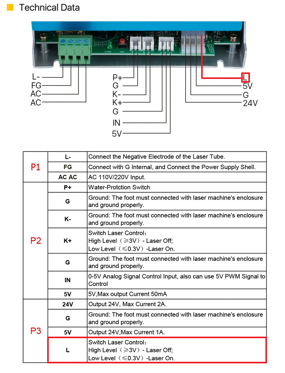
yes - pin2.3 (Fan Fet) of my smoothie pulls-down L terminal of my laser power supply like so:

I guess you can chose to use pins 2.4, 2.5, or 2.7 the same way. i chose 2.3 as the fet is “quicker/faster” than the others and i thought it wont hurt thinking fast engraving and such but frankly - all are much faster than required.

Correct.

Not sure what you mean. fire is part of the panel (digital panel) and triggered manually if required. not connected to SKR.

Please use this information with the utmost care.
Cheers.

So if L is used to switch ON/OFF the laser how do you control the laser power? Through logic level shifter, like yassin in OP?

Hence SKR’s PWM’s Duty cycle. the longer the on-time vs the off-time = the lower the laser power is and vise versa (in our case laser output is inversely proportional to the voltage/frequency of the pwm).

I do understand (I think) this bit. I get that through PWM signal PSU will switch laser ON/OFF.
But how do you acctualy allow SKR to controll the laser output power?
I.e pin 3.25 is PWM capable, and as far as I understand will output 5v so can controll Laser PWM or IN in case of older PSUs. It is easy to do if I would disconnect the panel which is using this terminal, but how to have both in same time? Panel to set maximum output for 100% of the controller?

You can change pin functions as easily as editing the config. This is for the various smoothieware modules.

Thank you, Bonjour. It will be useful once I will figure out how to connect everything physically.
I am just unsure how I can control the same pin on PSU (labeled IN, or LASER PWM) both from the panel and from SKR board. Intuition is telling me that I should treat both as resistors, and put them in series…

Unless what squid is talking about is controling bot, laser power and laser switch with just one terminal on PSU - L. But I don’t think it is the case…

BIG thanks yassin. This thread looks as if it may be my salvation and getting rid of the mks-dlc v2.

The controller is connected to the power in series with the resistor dial to the IN pin on the psu.

You set your upper PWM limit on the board, so you can’t get more power than that upper limit. The dial controls the output of the board, giving you override control over the output, but no higher than the max output set in your PWM config.

1 Like

your k40 has a “analogue” potentiometer, right? Mine has a digital panel, but I am thinking of getting rid of that in favour of just simple pot. Alot easier to setup in series with a controller…

Mine has a digital panel. They do the same job as an analog dial. No need to double up or replace something that works. The downside to the digital display is the power drain on the very marginal 5V rail on the PSU. The 5V output has only a small amount of mA to work with - and everything else you put on that 5V rail sucks power and reduces the efficiency of the panel power control. A $10 5V switch-mode psu takes the load of the K40 PSU, and delivers a much cleaner supply, without the likelihood of ‘browning out’ due to excessive drain.

When converting K40s, I add in a 5V psu, a 24v PSU and leave the existing PSU only for laser power. The controller/steppers are powered from 24V, the accessories by 5V, the power to the panel comes from the PWM output by the controller. I don’t have an SKR, so I can’t say how robust their 5V transformation is.
The panel should be set to 100% and ignored for the purposes of overall power control, except when you want to override the power down, for some reason. All power management should come via the controller.

The process is:

  • Set your controller to give 100% PWM output.
  • Put a multimeter on the ground side of your tube to measure the mA
  • Adjust the panel to the setting you would use to reach the maximum power allowed by your tube - for arguments sake lets say it’s 15mA.
  • Measure the PWM input to the LPSU ‘IN’ at that setting - that gives you the maximum PWM output that matches your panel setting. That is the maximum power you want output by the controller.
  • The PWM output from the controller goes via the panel to the IN pin. The panel only acts as a manual limit on the controller output. It cannot go higher than the maximum PWM configured in the controller, but it can cut the power.
  • So, if you tell the controller to run at 80%, with the panel at 100%, there is no change to the PWM output by the controller. If at 50%, in theory it should deliver half the PWM output, but it never seems linear.
  • You can calibrate it using a multimeter, stepping from 5% to 100% in 5% increments and reading the mA out of the tube.

In normal use, you would leave the panel at 100 and all power is controlled by the controller, via the job submitted, just as my RuiDa-controlled machine has the dial operate on adjusting the power level for the current job - so my job has me cutting at 85% power at 100mm/s, but I wind down the dial because it’s a little too fierce. Not something you do every day, but I occasionally use it to run a second pass at lower power if the part didn’t release cleanly or if the engraving is too hot.

The main difference is that on most bigger machines, the LPSU has a pot inside that you can adjust to meet the maximum power recommended for your tube, and the cheaper ones that use the K40-style PSUs don’t. Just a LOPT that boosts whatever signal up to whatever output. That’s why K40s are easy to burn out the tube - there is no way to set an upper limit on the LOPT (Line Output Power Transformer - the device that puts out 20KV). On an advance PSU, there’s no need to calibrate the PWM output, because you can adjust the upper limit of the PSU.

Of course you could replace the crap multi-volt PSU that comes with the K40 with a better 40W PSU with power adjustment, and make things a lot simpler.

Never forget, a lot of ‘info’ written about K40s is from the perspective of a spotty 17 year old in his garage, with little attention to actual electronic theory, figures given and measured, and filtered through the opinions of people that haven’t a clue what they are talking about.

The info from the guys at C3D will be much more informative than anything found on FB or Reddit.

2 Likes

Squid… One thing I’m confused about (same as Yassin): Isn’t that pin pulled high to about 24V when it isn’t enabled? I want to try your method. I never saw this post before today and had worked out a similar solution to Yassin except on a SKR1.4 using the Servo and Probe ports with logic converter on PWM but not EN (since 3.3v is enough to turn it off). I was running Marlin, and it SUCKS for laser, so here I am trying to convert to Smoothie. It was firing with same pin config I had setup in Marlin, but power level control seemed way off. Too dark even at 3% in LB

So you are saying to connect PSU-PWM in pin directly to the Fan Port negative (2.3) terminal? If I read that pin while idle and nothing connected, I get 23.75V ish. Then I connected it the way I THINK you mean, direct to PWM, and blipped power on for half second showing approx 20V. I assume that is too high to apply to the PWM pin since it’s 5V logic? Maybe I’m incorrect about that.

I just don’t want to cook the 5V rail on my PSU or fry my SKR so I don’t want to continue until I understand whatever it is that I’m missing. I’m not a complete dummy but this is making me feel stupid LOL

So what am I missing? I removed the digital pot/control panel months ago when I switched to Marlin from stock so currently don’t have it connected at all. I do have a 10k pot on-hand if I need it… Does the pot have to be connected to pull it down to 5V level? That’s the major difference in my setup, no Pot. It sounds so simple when I read it, but I’m completely misunderstanding something here because this doesn’t seem correct…

But you are not connecting positive pin of fan terminal to PSU, only GND, which is common for PSU and SKR. So it doesn’t really matter how high voltage is on FAN terminal, so long as PWM is only connected to GND pin of FAN.

Hedeon, I get that, yes the POS pin of fan is always at 24v,
But the fan GND pin is also at 24v until the laser fires, THEN it’s pulled to GND. Isn’t that going to toast a 5V regulator on the LPSU or something? That’s what I’m confused about.

I’m gonna re-read this entire post for the 12th time, but it still isn’t clicking for me what exactly is correct. I wish I could see a simple sketch of a schematic or something of the whole setup. The one showing the FET is helpful, but doesn’t tell the whole story. I’m teetering right on the edge of having this connected and having a working machine again, but have hit a wall with this. It’s just the ONE pin holding me up dangit LOL

I guess the worst that can happen is I lose another $50 from killing the SKR or $100 from toasting the PSU, then several days downtime while I wait on a new one.

Guys, it’s simpler than you think.

LPSU Laser switch control terminal is whats controlling the tube’s power. this leg is pulled-up internally inside the PSU to TTL level by the analog pot or digital panel so the laser is OFF by default because the power output is inversely proportional to the laser switch control terminal voltage.

Now, if you connect the SKR fan fet ground leg (do not touch the 24VBB leg) to the PSU Laser switch control terminal you are pulling-down the voltage from high to low e.g. - the more on-time vs the off-time the fet is - the more power the laser output will be. the fet ground leg PWM ground of the PSU Laser switch = lowering the voltage input = higher laser output.

Hope this makes things a bit more clearer.
And whatever you do - keep safe.

1 Like