QUESTION: Why are you converting to a bitmap? If it is to share the layout with a purchaser, do this instead… As a vector, open the Preview window. There, you can save the image as a PNG or JPG file. Converting that to a different image format like TIFF or BMP is easy.
I’d like to suggest backing up and offering a detailed description of the end result you are after, including pictures and illustrations to help us “see” the goal. It is not clear to me from your wording or the picture you shared. Let’s get an agreed understanding of your goal, and then we can offer some suggestions for how to get there - Thanks.
Marcus_Wakefield Yes, you are right. I want to remove majority of surface.
I can attach project with initial vectors that cannot do this job. And then I has been created through clumsy process - create bitmap, extract bitmap, invert bitmap with graphics magick, reimport bitmap … and attempt to burn.
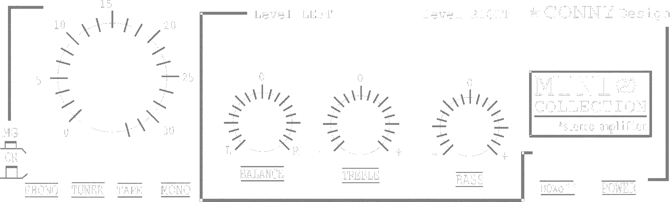
This is an original file: amplifier.lbrn2 (2.0 MB)
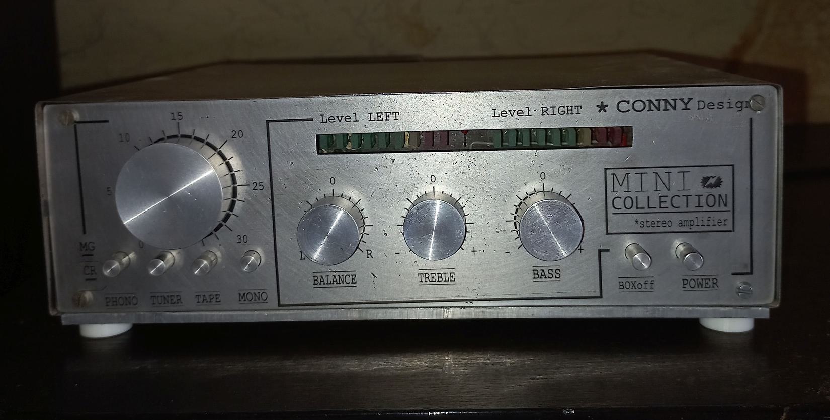
it has background illustrative photo that is never intended to be burned. It has been obtained from magazine and it serves for orientation only - does not fully fit to the real object.
This file has been produced after many unpleasant steps like converting to bitmap and using external tools that I want to avoid: amplifier2.lbrn2 (3.2 MB)
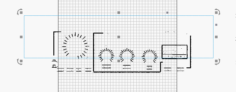
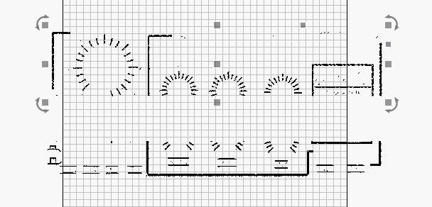
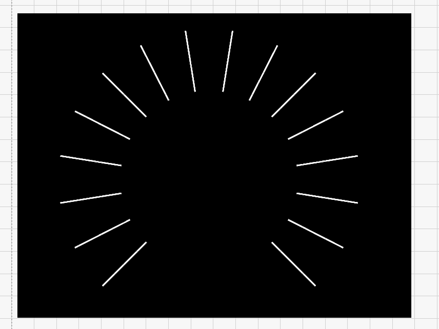
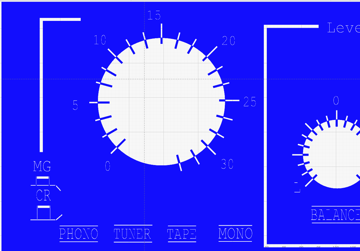
I’ve welded and tidied up some of the overlapping graphics and moved everything to the Blue C01 layer to make it more straightforward. I’ve then just added an all-encompassing rectangle to the same layer. The result of this is that everything inside it gets inverted. like this partial screenshot:
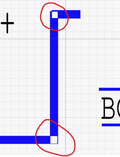
Nice job @Marcus_Wakefield, thank you for the assist. Only a minor suggestion, I might weld the circular “tick-marks” into the fill, so the marks inside the circles are not removing what is already there. Otherwise, awesome suggested solution.
Thanks @Rick . It wasn’t actually meant to be a complete solution, just a guide really. I just thought I’d perform a little bit of tidying up while I was there
Thanks, I did not know that are vectors are XOR merged together.
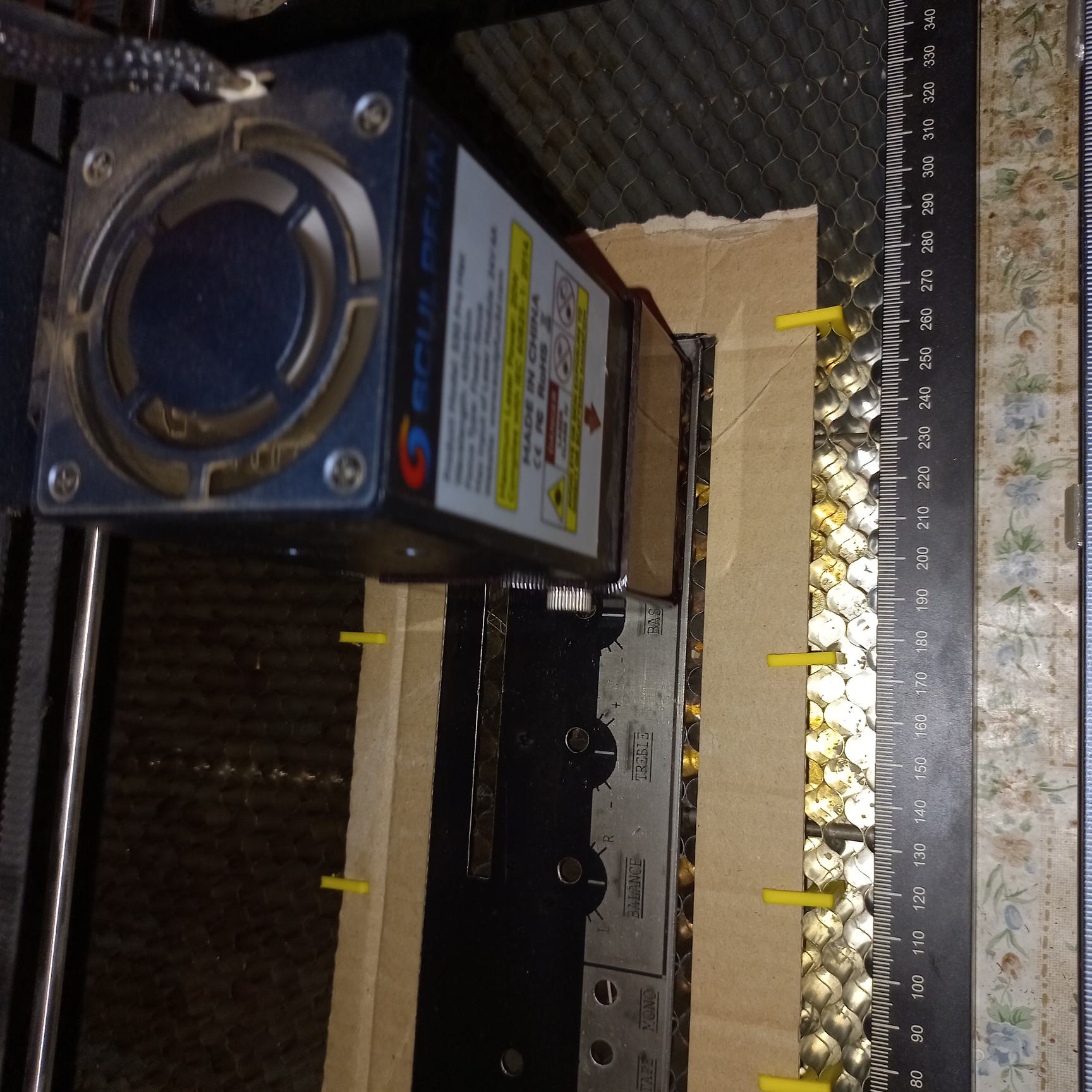
@ Rick The area behind circle is not visible, because there should be physical knob.
I have planned to use a same approach for electronic PCB’s. 20W LASER do not touch copped, but the paint would be vaporised. The small problem is that LASER beam is 0,3mm thick for my case.
Yes, it is interesting that even this fine detail could be created in a paint - it might be an art. Small rounding might look better, but this was my first attempt to create something like this.
For PCB this would be a failure, unless you want create a fuse.
Which line distance would you choose? 0,3mm (beam diameter) seems to be too wide. May be something between 0.15 ~ 0.2mm.