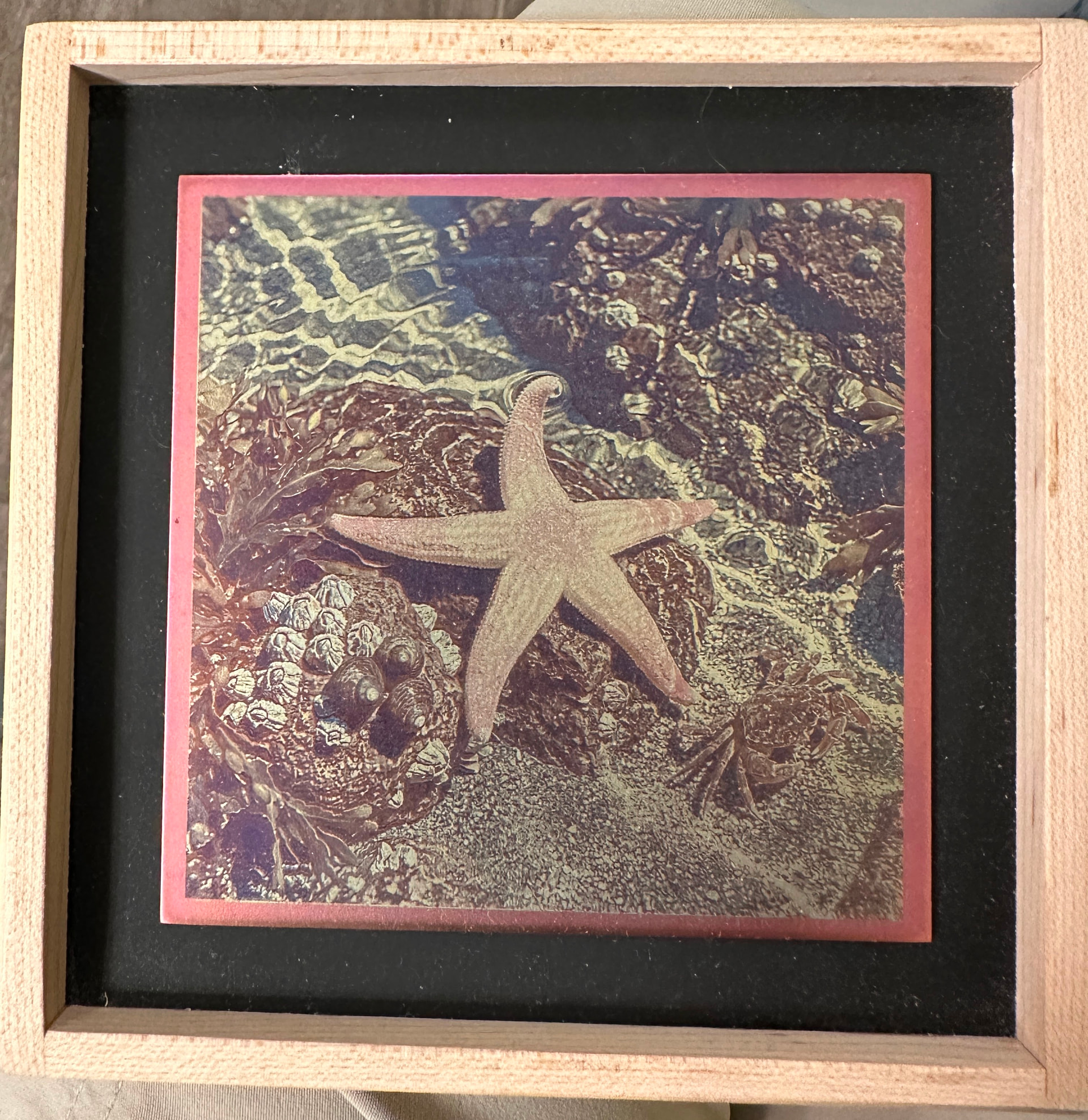
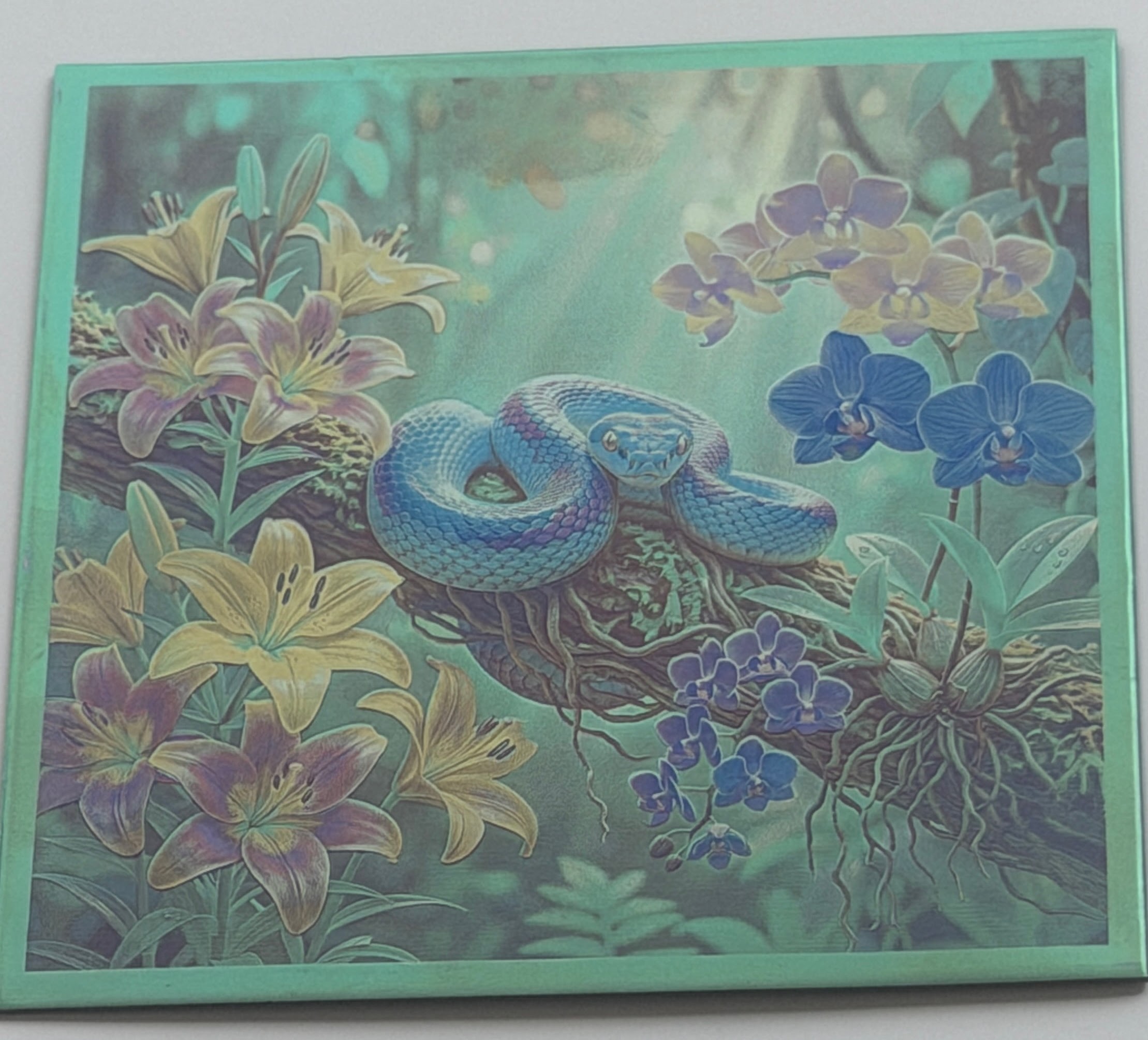
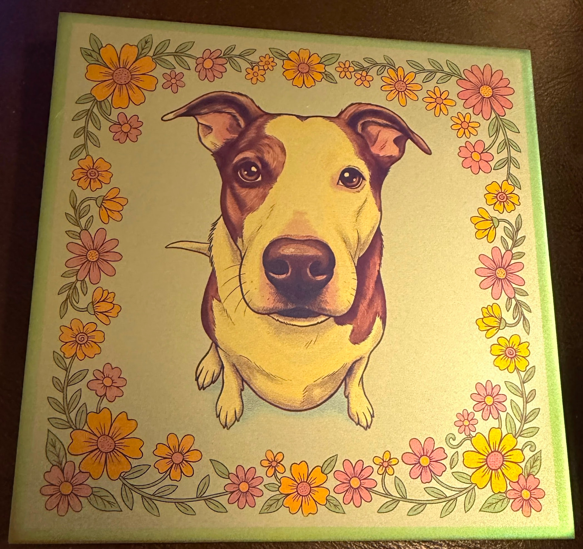
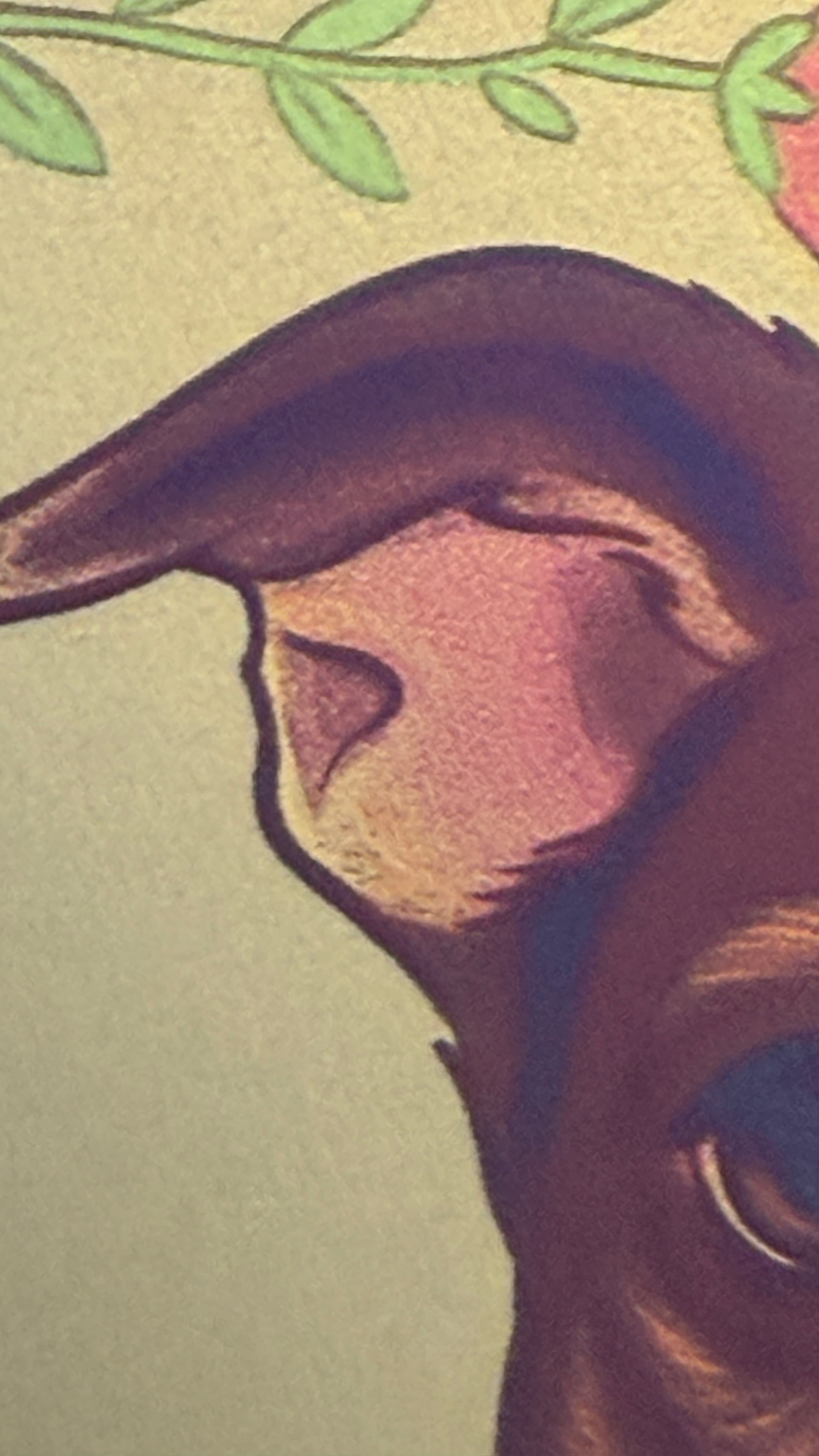
I invented a way to make 508 DPI full-color images by alternately anodizing and ablating titanium

I am having a blast developing a way to use my xTool F1 to anodize/ablate full-color dithered mosaic images onto titanium. The images are 508 DPI, and I use python scripts to process photos or AI images into PNG files to ablate for the different colors. I anodize the bare metal to the highest voltage color, ablate the oxide off in the areas that should have the next color, anodize at that next voltage, ablate again, etc. The software blends the 5 to 10 anodized colors dots to make it seem like there are way more colors.

Here’s an album of the dog showing the source images each ablation and anodization, and the resulting image.

Here’s my GitHub site with a gallery and a lot more information about how I do this.

I would love to find collaborators if others are interested in doing this!


9 Likes

I forgot to explain that the last photo is my anodizing station: power supply, temperature control, and anodizing rig to facilitate dunking the sheets in TSP solution with voltage (up to 91 volts) applied.

Also, I should note that I find the pieces difficult to photograph. The thin film effects tend to freak out my phone camera. The pieces actually look better in person, especially when the angle to the light source is right and the anodized metal has a lovely glint. I put a video trying to show the glint in my GitHub site.

2 Likes

Wow! This is incredible! Amazing work!

Impressive!

Incredible! Thanks for sharing!

Hi Mark

Humble diode laser engraver here, with not much more than a cursory knowledge of what your doing but could I ask, Does the anodising assist greatly in the process and specific oxide production or is it only to get you into a specific colour range for image appearance.

Nice website and info!

Well done.

1 Like

This is wicked!

Peter,

Thank you (and the others) for your positive feedback!

You ask an excellent question. The anodizing is actually what fully produces the color. The anodized oxide is the result, not an enhancement for the laser producing color.

The F1 isn’t very powerful, and I’m not using it to directly apply the oxide at all. Its role is to remove oxide in areas that will receive the next color oxide layer from the anodizing. This is a relatively low power operation so it goes pretty fast using the galvo laser (IR). All the ablation does is remove the higher voltage oxide(s) in the right areas for the next color so the resulting bare metal anodizes to that color. Your two watt IR laser should work fine for this.

There is some texture in the metal left by the laser, so the anodized layer is a little matte, but it still has a lovely anodized glint that I don’t think direct oxidation would replicate. And the colors are quite vivid and very consistent. Also, I think the matte metal surface helps me get a robust oxide layer. The sheets really light up with light from a full spectrum source when the light and piece are aligned so the source’s light reflects directly to the viewer’s eye. Off angle isn’t as vibrant which gives the pieces a dynamic aspect. The glint is more diffuse from the slightly matte surface which makes the pieces look better from wider angles

The oxide layers have no inherent color, it’s all derived from the reflection, refraction, and interference of the light interacting with the nanometers thick oxide. It’s called thin film interference which is also what gives bubbles and oil slicks their rainbow colors. The exact colors are entirely a result of the voltage I use for anodizing (with many other variables carefully controlled). During anodizing, the thickness of the oxide keeps increasing until its resistance is high enough to stop the oxidation process, so higher voltage makes thicker oxide. Different thickness oxides make different colors. To me, it all seems quite magical.

I too am a humble diode laser user. The F1 has two diodes: blue and IR. The IR is is technically a DPSS (Diode-Pumped Solid-State) laser, not a standard direct diode, but still a diode. :slight_smile:

I really appreciate your question!

3 Likes

This being on Titanium, I am guessing you are using the IR diode, right?

Mike,

Yes, strictly IR. If I use the blue diode, it doesn’t affect the oxide at all. In fact, the oxide is amazing tough in most ways. AI tells me it can scratch, but I’ve never seen that happen. Sanding it (reusing a sheet that didn’t work out the first time) takes way longer than first ablating off the oxide with the laser and then sanding. The oxide is impervious to sunshine and most chemicals. It gets fingerprints, but those clean right off with windex or isopropyl alcohol.

The two watt IR has enough power to darken the titanium directly, but it’s slow, and it makes a rough charcoal surface that takes a lot of cleaning and wants to smudge on the surrounding areas. I use direct oxidizing for simulating lead in stained glass theme pieces, but otherwise it doesn’t look right because it turns ghostly when viewed from an angle and has no glint.

1 Like

This is super cool. I was thinking about it initially from a silkscreen printing perspective, but that’s not quite right (subsequent colors are not layered - other than adjacent dots). It’s more like each layer is a new stencil - it is the removing of the previous layer(s) that allows the metal to be exposed and thus anodized at the new voltage - there is no layering like in a traditional print.

So you are combing traditional printing (layering via stencil, silkscreen, plate) and digital (like RGB) where adjacent dots trick the eyes into seeing a weighted color. Using projective (right word?) ā€œcodingā€ in a printing (CYMK like) output.

Am I getting it correctly?

1 Like

Tony,

You got it right! :grinning_face:

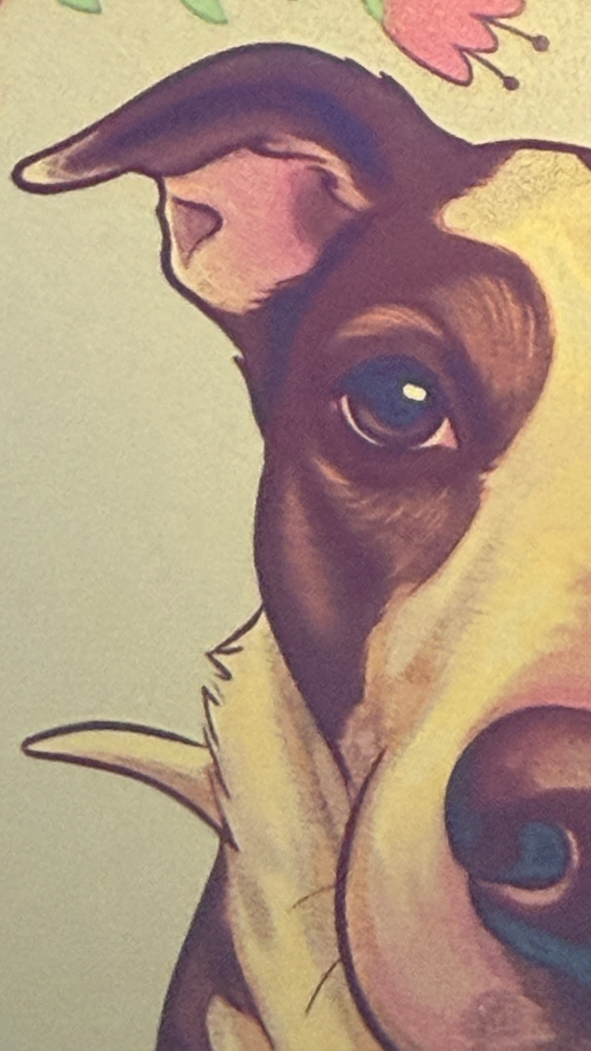
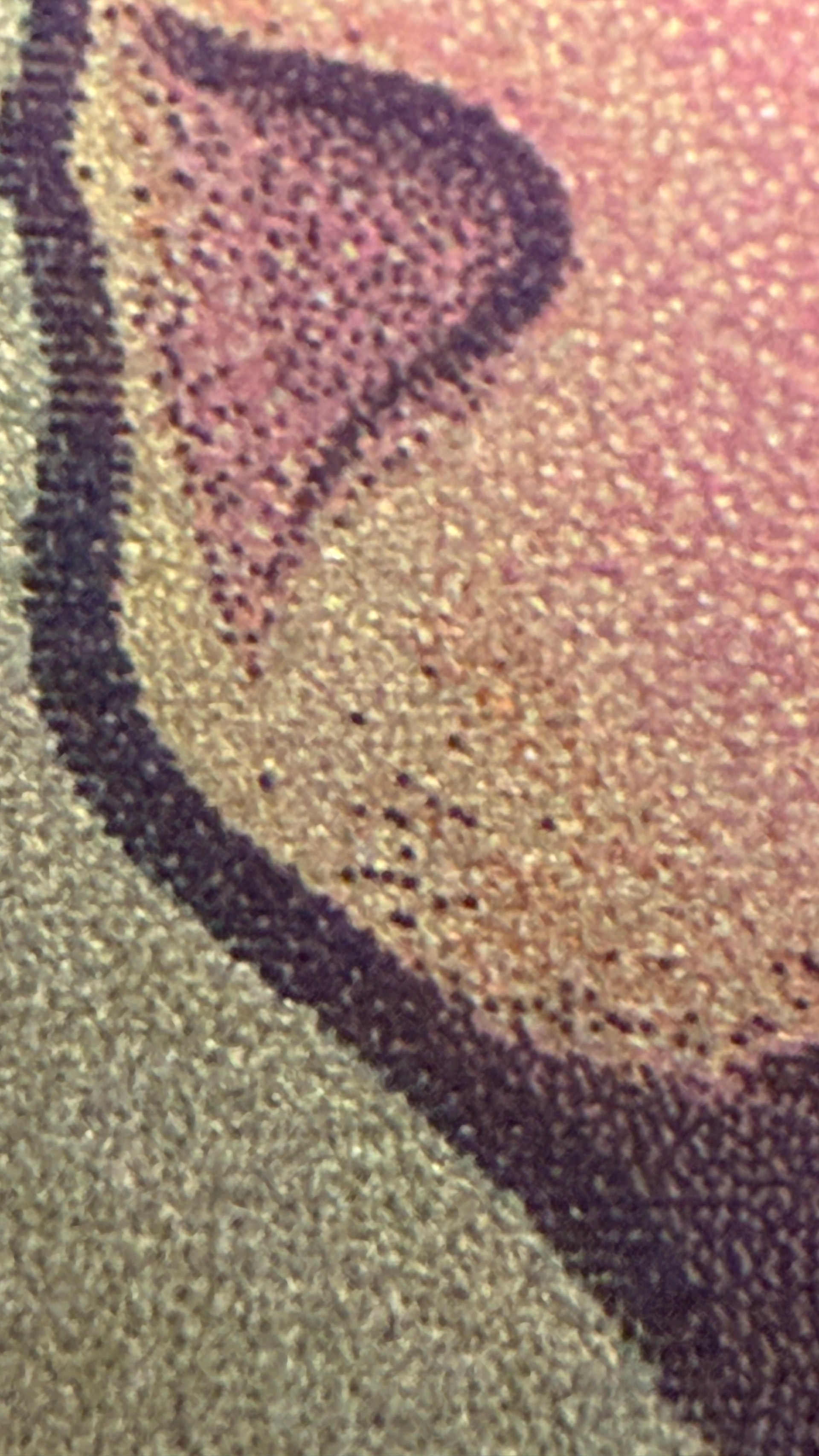
It’s a mosaic of single color ā€œtilesā€, and the tiles can’t overlap or combine colors. So there are literally only as many colors on the metal as anodizing dunks. The apperance of many more colors comes from dithering (Floyd-Steinberg) those few colors together. I attached three progressively closer images of a slightly different dog image (I already gave away the better one) to show the dithering. A lot f the work in this project has been finding better ways to control that dithering to get good results.

I experimented with CYMK-like ideas, but that ended up with separations that required a lot of adjustments and tinkering to look ok. The newest ā€œcolorimetricā€ separation engine tends to get much better results without tinkering. It knows a palette of 13 colors I can anodize and calculates how to blend those to get the right appearance (if possible given the palette and luminance the oxide layers can provide) for each local area. Claude knows the details of this much better than I. If you’re interested, I can ask Claude for a description of that engine.

One way I think about this is that it’s a subtractive process. Each layer removes areas on the metal left by earlier layers and put its colors in those areas. If you look at the Google album linked above, you can see this evolve.

A recent breakthrough was the realization that the dots are actually bigger than their 508 DPI area (ablation seems to have a threshold for single dots and once that threshold is broken, there is a radius around the dot that also ablates). I think there are other sources of dot gain like heat from nearby dots just ablated causing the ablation to be more vigorous. I had a piece that had disappointing results: bands in a sky that should have had smooth gradient, aquamarine areas that should have been a different color, and a dragon that came out darker than desired. I reported these issues to Claude, speculated that maybe dots were bigger than we thought, and asked if there might be a way we could compensate for that. Claude responded that this was a ā€œtextbook dot gain situationā€ and claimed with confidence that we could add a feature to the separator to address that. Claude was right. I now have a --dot-gain feature (1.6 is a good value: 1.6x the 508 DPI radius). This feature generates a second ā€œmetalā€ proof that predicts what the piece will look like on metal. It actually predicted the issues I had just observed on the disappointing piece - a very happy outcome! A second --dot-gain-compensate feature adjusts for the dot gain. After compensation, the metal proof is a much more reliable predictor of what the image will look like on metal.


1 Like

I remember now, it was a previous topic about creating a standing wave in the oxide with a measured distance peak to peak and pitch angle..and some reading on oxide formation, all very interesting.

Maybe you could try some diffusion of the camera light/flash with some frosted plastic or other, to help with getting the best images of your work.

Thanks for the close-up’s Very cool, and a little hint of line interval. Did you try adjusting pixel dimensions to cope with the spot blooming.

Wow! Standing wave in the oxide sounds very sophisticated! I’ve only had the laser since February and know just enough about engraving to realize that I know very little. Yes, I too see a little line interval. I’m not sure how to adjust pixel dimensions (perhaps related to DPI?), and it may not be possible in XCS. I wanted to switch to LB to get away from XCS’s very bad habit of dithering my PNGs (ruined the whole point of what I am doing), but I made the mistake of updating the F1 firmware shortly after I bought it, and that firmware and LB are incompatible with each other. The published solution is to downgrade the firmware, but I found a way to get XCS to never dither before I downgraded, so now it’s not high priority. But maybe I should switch to get more control over the laser part of my work.

The dot gain adjustments greatly reduce the problems from the dot blooming, but I’m intrigued by the idea that pixel dimensions may be a variable I might be able to dial in to control that variable too. Compensating helps, but reducing will probably help even more, especially when still paired with the compensation.

Claude claims 508 DPI is about the finest resolution I can reasonably do on the F1, but your question makes me think perhaps I should challenge that assumption. It created PNGs carefully calculated to strictly fit 508 DPI so XCS wouldn’t dither when I set it to 508 DPI. That worked perfectly, and I haven’t revisited it. But I’m pretty sure the laser is doing more than 1 pulse per ā€œdotā€. Again, I’m not very knowledgeable about lasers, but perhaps that’s a good area for me to explore further. My dot gain success makes me realize that the physics of what’s actually happening on the oxide and metal matter in sometimes subtle ways. Plus, I’m intrigued with the idea of trying to make the ablation PNGs use the actual resolution of the laser. So many potential experiments and investigations and so little time!

I think using my SLR with manual settings and (as you suggested) consistent and more mindful lighting could help. I expect it would at least make my photos more consistent. Another potential experiment.

Thank you for your ideas!

My photo’s of jobs done are not good so I’m going to build a lightbox for the purpose..and should also be using the dlsr for the job…it’s just quick to upload from the phone.

I’m reasonably new to lasers and Ai so I wouldn’t put doubt on Claude, but where I started from was imagining the laser spot (applied energy) as a bowling ball dropped from various heights (power%) into a square frame (pixel). At increasing heights the ball starts to crater deeper into the sand and throws material outside the frame (bloom). Solution is to make the fame bigger.

Is Claude stuck on the idea of a specific resolution/pixel dimms.

I love your bowling ball metaphor!

Claude seemed a bit confused about the resolution of the laser, so I tried asking Gemini. Between the two, I think we’ve established that the F1 IR pulse is 0.03 mm diameter circle which is a bit surprising to me because according to my dot gain measurement, I’m getting isolated dots that are more like 0.08 mm. 508 DPI is a 0.05mm grid, and I found that adjusting for 1.6x that diameter gets good results in the dot gain compensation. It seems my settings to get past the threshold for ablating to work on isolated dots is causing thermal bloom that is then removing oxide far beyond the edge of the pulse circle.

Both Claude and Gemini think that the F1’s ā€œalign the dotsā€ focus isn’t very accurate and that being out of focus would increase the dot size and increase the power threshold to accomplish ablation, both of which seem likely to increase the dot gain. They suggest I could do a ā€œfocus ramp testā€ by tilting a sheet a bit and ablating different settings to see where they accomplish the thinnest ablation. That seems fine, but if I ever refocus the laser for anything else, I’ll lose that calibration. And now I’m a little afraid to refocus because that may invalidate my 1.6 dot gain measurement. But I guess a single ā€œfocus rampā€ might at least give me an idea of how sensitive the process is to focus.

There are so many variables to control in the quest for consistent and pleasing results!

Did you mention the dot gain to one ai and then ask the other to confirm if the first ai was correct. If so, it may be confirmation bias. I am not subscribed to ai so every conversation is new and it has no previous info the refer back to and therefore doesn’t get tunnel vision.

Last evening you mentioned that you thought the laser was firing twice per px (if I’m remembering correctly). If that is so, then that’s the reason for the bloom.

In the analogy, the ball is the ā€˜Laser Dot’..unchangable, The impression in the sand is the ā€˜laser Spot’..variable by power%, and the Frame is the Pixel dimensions..variable by image resolution adjustment.

I simply ballparked an estimation for the bloom at x1.2gain and adjusted the image resolution accordingly. -1.2 was later confirmed by ai’s own reconning without my mentioning it. Pixel dimensions are also dependant on applied power% and image quality after adjustment, so after a certain point the image overall size must be adapted if the applied power% is to be increased by large amounts.

At this point the quality you are achieving looks fantastic and you have a technique benchmark. How do think you could tweak it.

I agree confirmation bias is a risk, especially in earlier days when the models were overly sycophantic and tended to agree with the human to a fault. Claude at least has balanced this better recently, but it’s still a problem. In this case, I gave Gemini wrong units on my dot duration so it came up with a lot of interesting but off base theories, and I was fascinating to see how thoroughly Claude (and almost gleefully?) debunked those.

After further ā€œresearchā€ and interaction with the AI’s I’m convinced that it’s not firing multiple times per dot. It seems the DPI setting is about the grid in which the 0.03 mm dots are fired and the dot size is fixed? I’m still not sure how the XCS dithering interacts with this, but that doesn’t matter because I’ve reliably bypassed that dithering because it’s harmful to my process.

It’s great that we independently came up with the dot gain (bloom) estimation and mitigation. I’m very intrigued by your straightforward approach of adjusting the resolution. I’m wondering if this is worth a try in my system and will brainstorm with Claude about that. Thank you for sharing that insight!

I enjoy exploring these possible dead ends because sometimes they pay off and I always learn from them. I am an engineer and work at an engineering school. I believe engineering is all about the scientific method and actually trying stuff. I like to tell prospective students about how Edison and his team found lots of ways to not make a lightbulb before they found a viable one.

Had a funny moment earlier where ā€˜Brave’ gave me a workflow for channels splitting/decomposing in Gimp, I questioned it on details and it promptly retracted it’s advice…and apologised. Pat on the head ā€œit’s ok buddy we all make mistakesā€.

Speaking of which, I must apologise as Dot size is variable…by focus adjustment, but I was assuming optimal. I downloaded Python but got lost in installation terminology. I wanted to copy/paste the script from ā€˜nothing.it’ (Great work) into Gimp but got lost in that process previously also, but is it true 1:1 tonal value selection or just another posterization technique. Ai says it is ā€˜every pixel’ 1:1 on a layer per #/luminosity value basis.

Originally I simply wanted to reduce the image palette to 8 tones to mach the human perception for tonal shift threshold..but 12 would be better > Take the output values from lightburn Gcode to find the optimal power% per tone on the material and calibrate the two to give WYSIWYG.

It’s a grid and a set of values and I can’t get my head around why it isn’t easily doable, maybe I’m oversimplifying but from what I remember of ā€˜Basic’ programming its not a big deal. I’m a gardener/horticulture/landscaper and a coffee roaster and I model build in my mind and operate/run the model under various conditions…so its very Newtonian.

If I’m not mistaken, I think any laser needs to be pumped up. This raises the energy level of the molecules enough they emit an EMF energy when the molecules go back to an unexcited state. Being in an excited state allows collisions between molecules. Those collisions help support amplification by colliding of lower energy molecules.

I know the first laser (ruby diode) used a standard photo flash used in photography to pump up the ruby core.

I would think if you have a true laser diode, there must be some kind of cavity or area that’s used to AMPLIFY the energy.

Q-switch fiber and IR diodes on these machine pulse naturally because of the materials used in construction. At least with Q-switch fiber machine, you have a very small range of pulses/s you can select.

This is a good video from JPT about how the source operates, too bad it doesn’t cover the MOPA part… :thinking: Still worth watching.

Here’s two articles on coloring with a laser. Both of these were done by a group of engineers and programmers to get it right. This is also how I’ve been working with it.

Laser-induced plasmonic colours on metals.

Open Access proceedings Journal of Physics.

I’ve have had lots of hours trying to make color work, just by the laser. However I’ve found when I change sizes, the colors change… So I kind of lost interest, with a stack of stainless that was wasted.


Your images or results are very good, most likely the best hobby results I’ve seen.

So I’m curious if the colors change with a physical size change with the same settings? It’s relatively Can you do 4 of these on one piece of stainless without any more processing other than what you’re doing?

I’m going to have to take time to take to figure out what you’re doing and see the actual process you’re using.

Thanks for the post, we like this kind of stuff.. :thinking:

Love seeing it, great work.

:grinning_cat: