I invented a way to make 508 DPI full-color images by alternately anodizing and ablating titanium

Pete,

AI gets things wrong fairly often. I’ve given mine standing instructions to just own up to it and move on. It sounds like Brave did just that. At this point, I have Claude (Cowork) keeping a running record of findings, and on its own it decided to keep a list of things to not bring up again because I proved them wrong. :slight_smile:

No need to apologize about dot size! I was thinking the laser might adjust the dot size which is clearly not the case for my laser at least. You got me on the right track. :+1:

For Python installation, I suggest you ask AI for help. You can even copy and paste the errors you’re getting into AI, and I bet it will help. If Brave doesn’t do a good job (I’ve never used it), I suggest trying Gemini (gemini.google.com). If you have a gmail account, you already have Gemini for free. I’m pretty sure it will be able to guide you through the installation. If the script uses libraries ask Gemini for commands to install them using the built in Python module installation option.

It’s a great idea to ask AI to explain Povilas’s script!

It is easy to make a set of values for the grid. The hard part is knowing what colors those values can assume (measuring the palette) and getting them arranged to produce the perception of lots more colors that actually look right. I have spent months on this. AI can write the code now, so you’re right that coding is now easy (although you’ll need a strong AI model to get it right).

I would happily share my separator script if you want to try it. It’s way bigger than the one from nothing.it and has lots of options, but I can also provide an extensive manual (full disclosure - it will be AI written). And I’ll make sure the manual has a starting command that will give you at least a decent set of PNGs to start. I think the script is likely fully applicable to what you want to do, but you would want to use the “footprint” PNG files for direct laser coloring because they don’t overlap. My anodize/ablate/anodize process tolerates multiple ablations of the same area of metal with no downside that I’ve noticed (it’s actually a feature because I always get color everywhere even if I don’t get perfect registration for every ablation), but I don’t think direct coloring would work well if you color the same are multiple times. It would be easy for me to make an option to adjust the footprint PNGs if you need something different from what it does now. If you’re interested, I could send you the script and/or a set of files from a sample separation that you could check out.

I like you you describe building a model in your mind and operate it under various conditions! My brain is very algorithmic, and I can’t remember random facts (used to have to derive the algebra rules while taking the test because I couldn’t remember them). So I’m thriving in this world where I have algorithms to prompt AI, use and modify scripts that implement algorithms, and use experimentation to develop my image coloring process. It sounds like you have a strong algorithmic streak too. :+1:
Hi Jack!

Thank you for your kind encouragement and for the links! You are helping me realize it would be a good idea to learn more about how my marvelous laser actually works. I’ll check out the links you provided. I’m glad you like this kind of stuff, and I’m enjoying interacting with humans about it instead of AI. :+1:

I am in awe of what Povilas accomplished (link in my GitHub site). I did just enough attempts at coloring directly with the laser (steel, brass, titanium) to appreciate how much calibration they did to get the amazing results they did. I found that I got different colors in different areas on the metal (corners didn’t get as hot), so I would have had to somehow adjust settings based on galvo angle. Plus, I don’t think my xTool F1 is powerful enough to do direct coloring well.

Now that I have dialed in the anodizing process, I get the same robust color whether it’s a single dot or a large patch and regardless of where it is on the metal. I’m really hoping others will try this, and I put a lot of work into documenting what I learned so others can get a jump start. I will happily share my scripts if you want to take another run at coloring metal using a different approach. :slight_smile: I am excited that you want to take the time to figure out what I’m doing, I welcome any and all questions, and I would love to help others get started doing this! I hope you check out the GitHub site (not written by AI), and if you do, please let me know if you have feedback.

To answer your question directly: I am using the same settings for all dots in each PNG. I think I’m over-ablating to get past the threshold needed to break the robust oxide layers my process produces (1.6x on individual dots, I think) which means I’m really blasting denser areas, but the dot-gain algorithm (and before I developed that, hand tweaking the separations) compensates well enough. That dog piece’s separation only got very minor tweaking; the dot gain compensation did the bulk of the work. Once an area is bare on the metal it gets the same color as any other bare spots when I do that anodization, regardless of where it is or the size of the area it is in. The color is determined by the depth of the oxide which is determined by the voltage, not by heat and all those tricky thermal issues. I have devised a way to apply the electric field uniformly every time, so I get the same color and consistent color every time. The trick is in properly separating the image into the dithered mosaic so it looks good on the metal. That part has to happen no matter how the metal gets anodized in the end or which metal it is.

I’m using titanium, not stainless. My anodizing bath is small, so I’m doing small sheets (100 mm x 100mm). I’m not sure how much bigger I can go, although I did by some 100 mm x 150 mm sheets that I’ll try at some point. Another constraint is that the F1 can’t engrave much larger than I’m already doing (150mm will go past its range). I haven’t tried it yet, but I developed the software to break a larger image across multiple sheets that I can combine after crafting them separately. I don’t know how obtrusive the seams will be. If I can find a way to get good anodized layers on larger sheets and if I get a laser that can ablate larger areas, I believe the process would then produce consistent colors regardless of size.

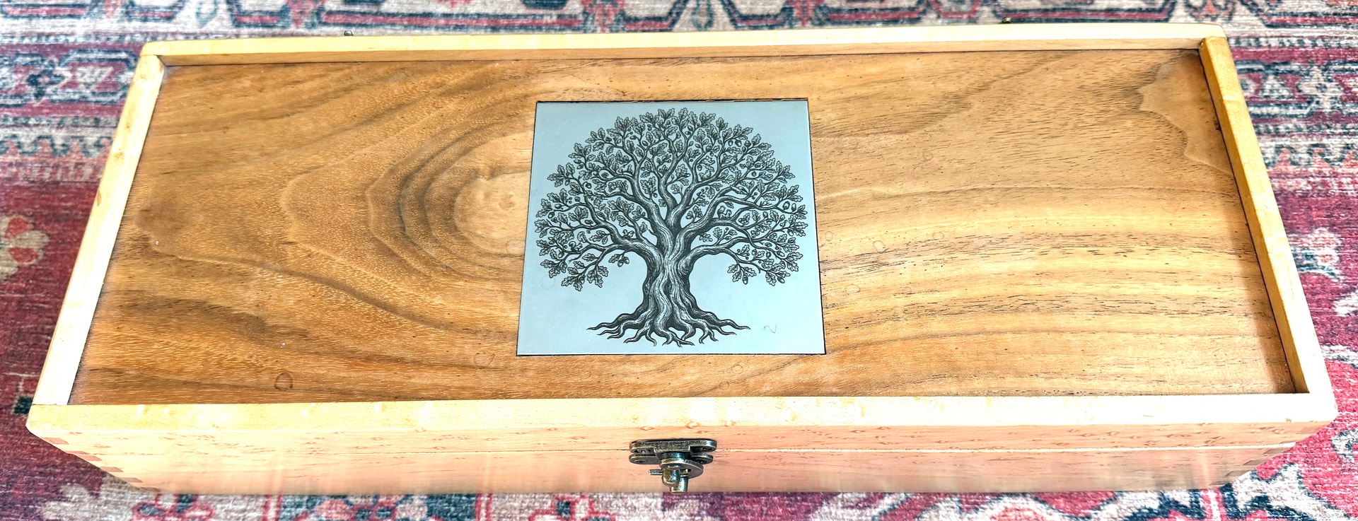
I found my xTool F1 has enough power to put a nice brown oxide directly on 304 stainless if I give it enough time and power. I made a fun tree (SVG from Etsy) image on a 100 mm square piece of that I embedded in the top of a box I made years ago for my Magic The Gathering stuff. Maybe you can do something fun like that with your stack of steel?

2 Likes

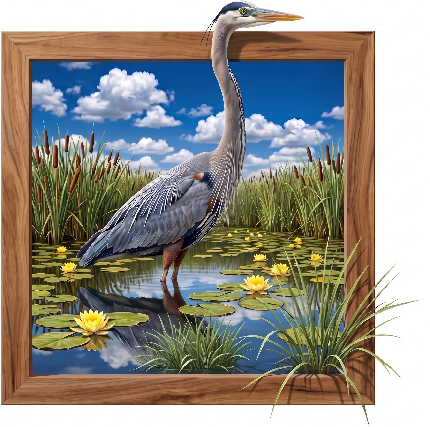
Inspired by this post, I decided to try making a 3d effect myself. It’s a great blue heron. It’s not nearly as cool as the other one (AI, not a photo, and I don’t think the 3d is nearly as compelling in mine), but I’m mostly pleased with how the metal recreated the source. I made the image using Nano Banana 2.

The biggest defect I see is banding in the sky (way too abrupt transition from lighter blue to darker blue where there should be a smooth gradient). I’ve seen this before but not as clear cut, and I think this one will be a good test case for me to try to address this banding challenge. I think there is some of the same effect on the bird’s neck and body, and I’ll look into why there is a light band just under the bottom edge of the frame on top.

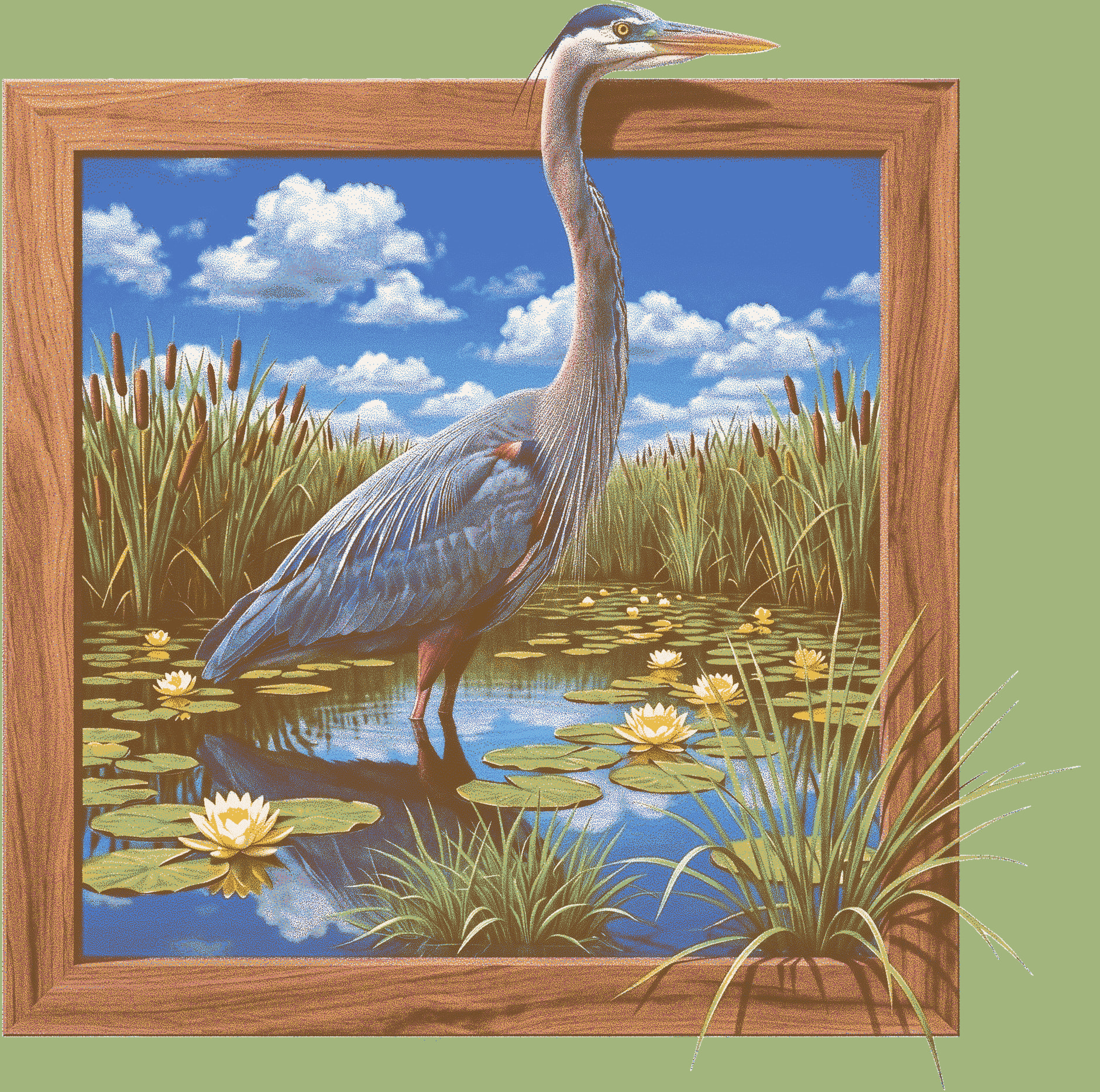
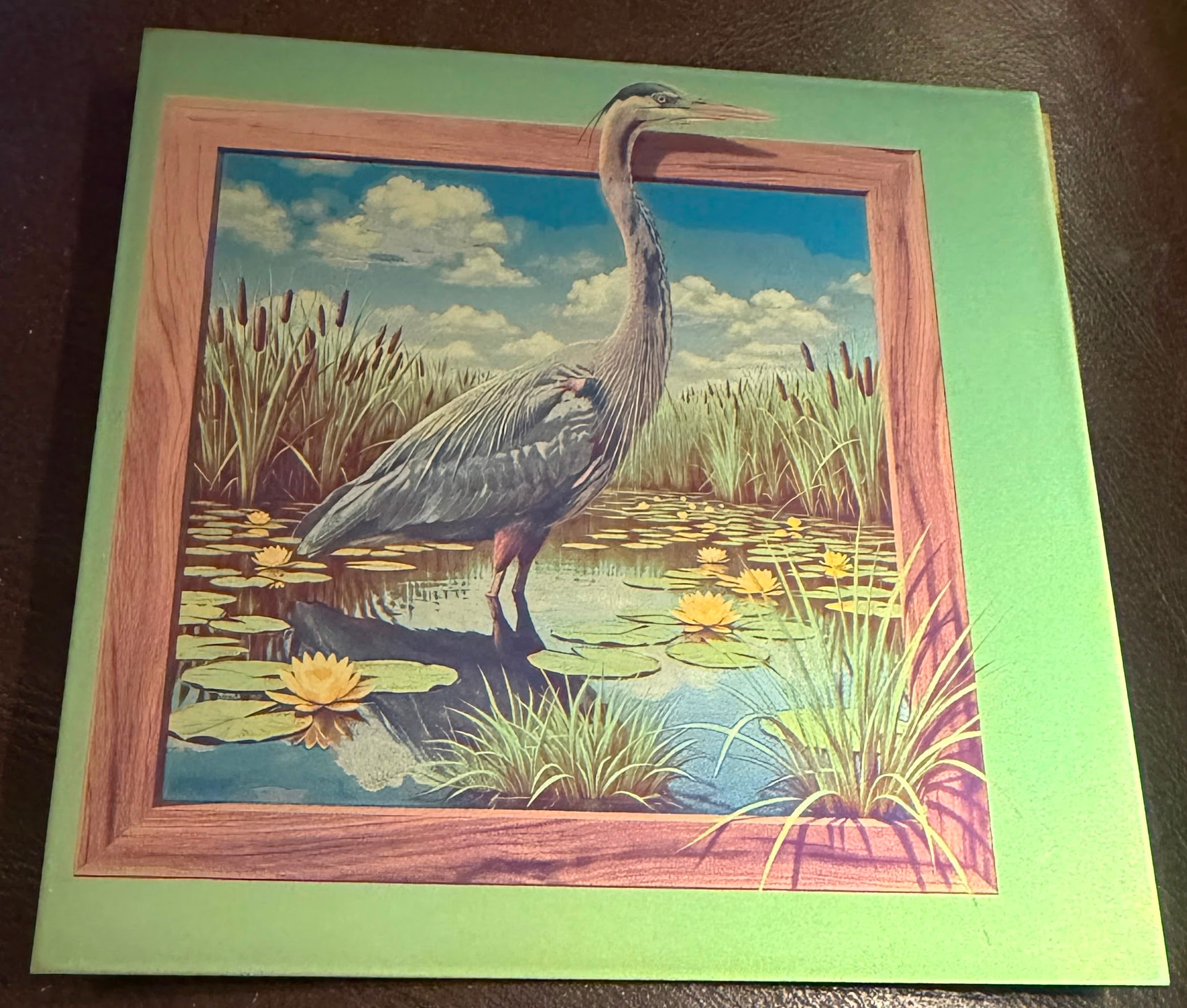
Here are: the source, the metal prediction proof my separator script produced, and a photo of the result. I did cheat a little and hand-edited the silver and cyan layers a tiny bit to restore the green the little patch the “remove the background” feature of the separator missed.


5 Likes

When you applied the ‘Manual change/adjustment’ was it using a curve tool or sliders and was it applied globally.

Would a local adjustment/mask have kept the changed area where you intended only.

Could the changed sky area (banding) have fallen within the threshold because that area is a different/lighter shade of blue to that above it.

Super job, regardless.

1 Like

Thank you!

My “manual adjustments” involved tweaking parameters in the separator script. I have been tempted to do local adjustments, but I am trying to avoid labor-intensive special cases. I’m investigating the possible causes of the banding now. So far, I’ve had pretty good success finding global principles that at least mostly address the local issues.

One possible theory about the banding is that I have the wrong hues in the palette for cyan and blue, so the colorimetric engine is not dithering correctly across the boundary. But I was surprised the boundary looks so abrupt. Trying to look at it with my phone on high magnification and macro, I think I see some dithering, but the two shades are close, so it’s hard to see individual dots.

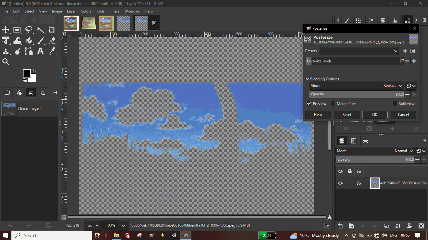
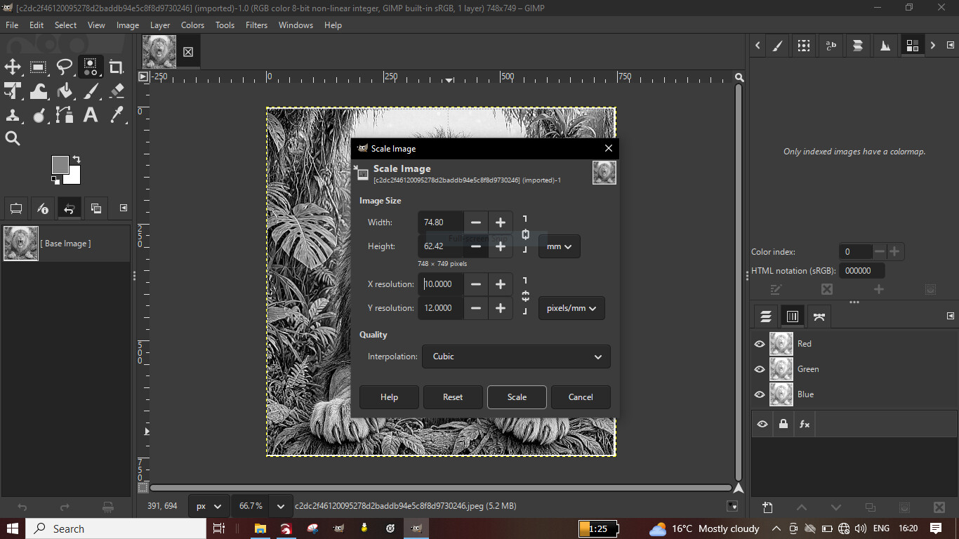
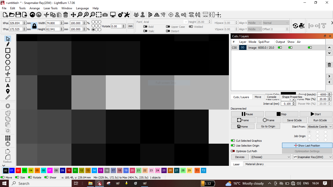
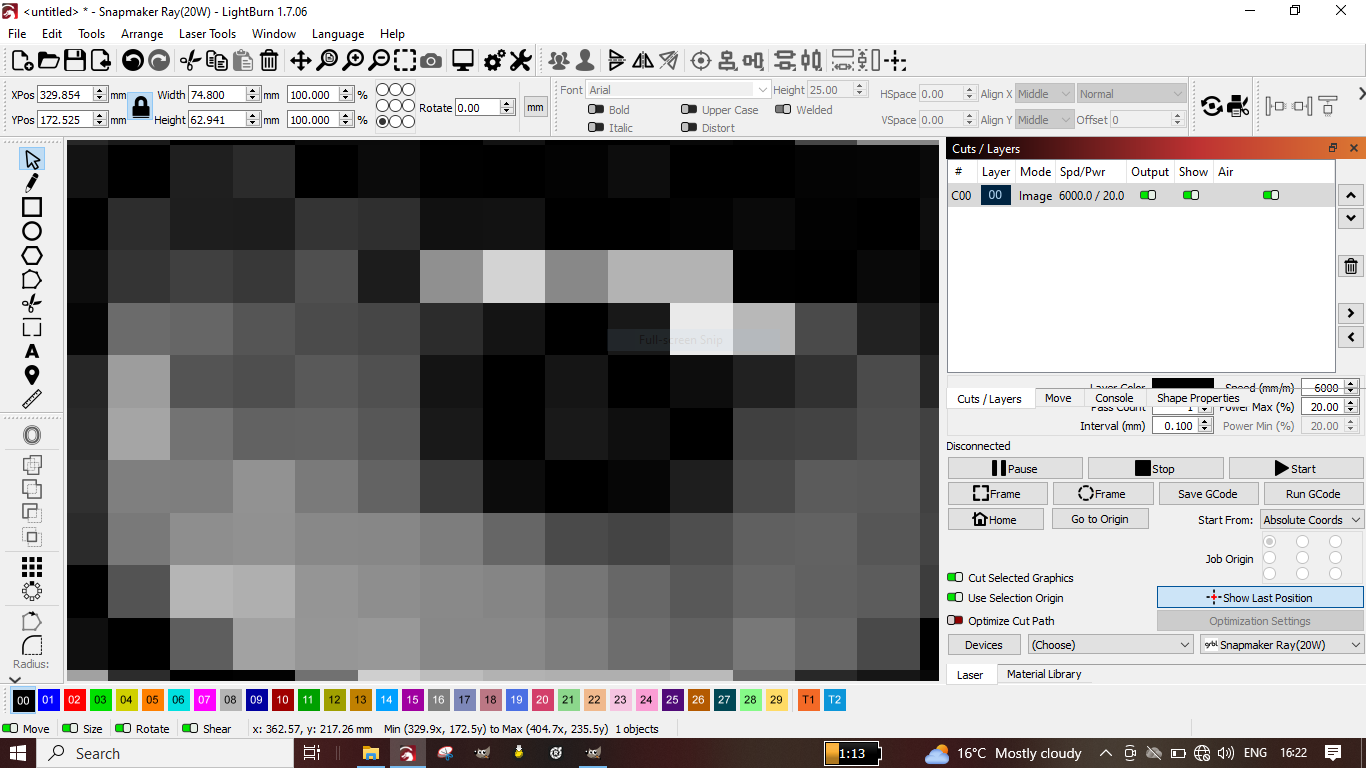
I took the crane image into gimp and applied levels. The banding in that specific area shows up at various level up to 57 levels. Here’s one I screen captured but I’m not sure how well it matches exactly.

Also a pixel dimm’s adjustment..from 0.1 to 0.12 on the x axis.

That’s a cool way to analyze the image! Thank you! I’ve never used or even seen gimp before, although I’m aware of people using it at Thayer School.

Which version of the crane image is this? I see you have the source, the photo of metal, and the proof in gimp.

The shape of the band in the sky on metal is different from this. In fact it correlates very closely with where the cyan layer ends. I went down a rabbit hole for the past couple of days investigating this and running tests. I think it has to do with over-ablating cyan so it actually produces enough heat oxide to affect the final voltage anodizing color. The sneaky part was the effect actually caused anodizing blue where cyan had been ablated to match the normal cyan color again. So it looked like those areas of blue weren’t ablating. Go figure!

I’m making a sheet to test a bunch of ablation settings for the lower voltage layers (silver and cyan), and I already have a new feature in the separator script to segregate dots in cyan and blue layers that happen to be over silver and cyan so I can run them using lower ablation settings. We’ll see if it works, and once I have this resolved I’ll report back.

Off the top of my head, it was not the finished job, and probably not the image with deep blue at top edge. I think the one I did was the lighter blue sky…as it might reveal the banding more subtly hidden. It appeared at many levels and I tried to find a close match to where it appears in your final job outcome.

The pixel dimm’s is cool, but be aware of overall image change…a good ai generator could surely deal with that.