Anything above this post takes away from the essence of the issue. The only thing I’ve included in the post below are questions that people have had trying to help me with my problem.
Equipment:
laser: JPT 50LP
Control board: JCZ Fiber Lite (bjjcz 32101lv)
Sino-galvo SG7110 scanner
OPEX F-theta 163 SCan Lens (working field 110x110 mm)
Software version: LightBurn 1.7.03
All experiments were carried out only on this equipment and in two programs: Lightburn and EZСAD
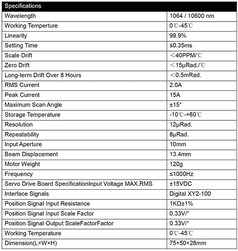
If you want to discuss the fact that I use high resolution and that my equipment does not support it. Please do not do it. Here is the specification:
Below I will explain why this is a wrong approach.
Also, I say in advance that the resolution of the original image does not affect the result. Also, the image format (jpg, png) does not affect the result. Many experiments were conducted. I wrote about some of them in the messages above.
I just don’t want to repeat these questions.
The file I used in my research:
test 00.lbrn2 (1,3 МБ)
The process of creating a research file:
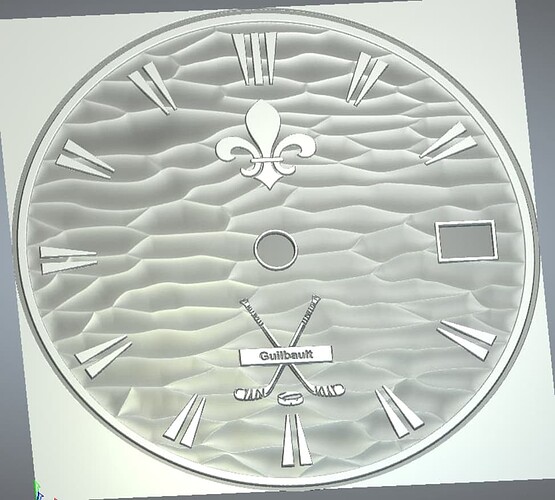
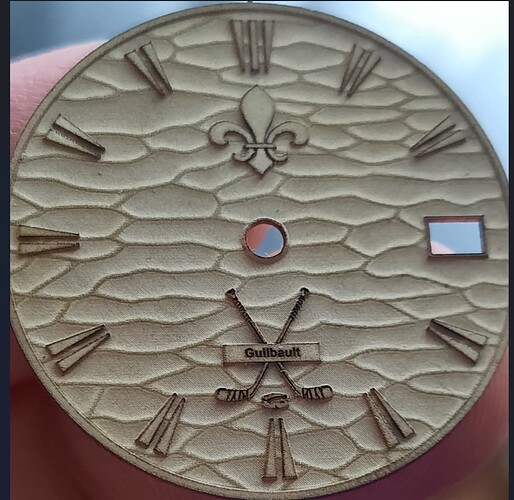
I created a 3D model from scratch:
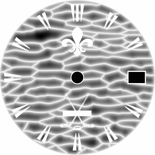
From this 3D model a grayscale height map was obtained:
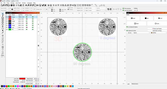
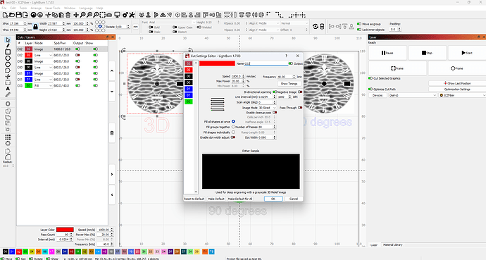
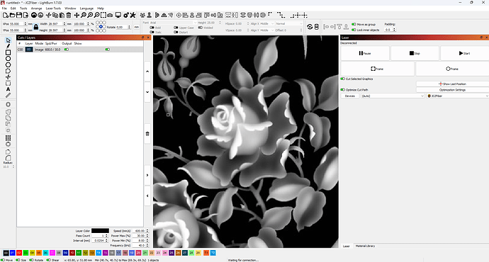
After that I loaded the grayscale height map file into Lightburn and prepared a working file:
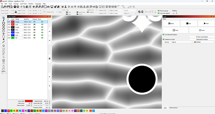
When zoomed in, the height map looks great, without any artifacts:
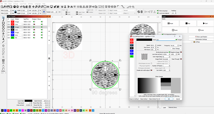
Now let’s look at what grayscale engraving is:
The image is engraved by changing the output power as a percentage between Min and Max Power, using Min Power for the lightest shades and Max Power for the darkest.
When you open a file in preview, the dark areas are what are engraved with more power, and the light areas with less.
Let’s move on to our file.
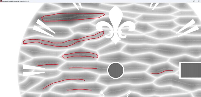
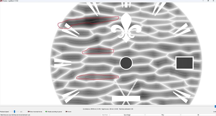
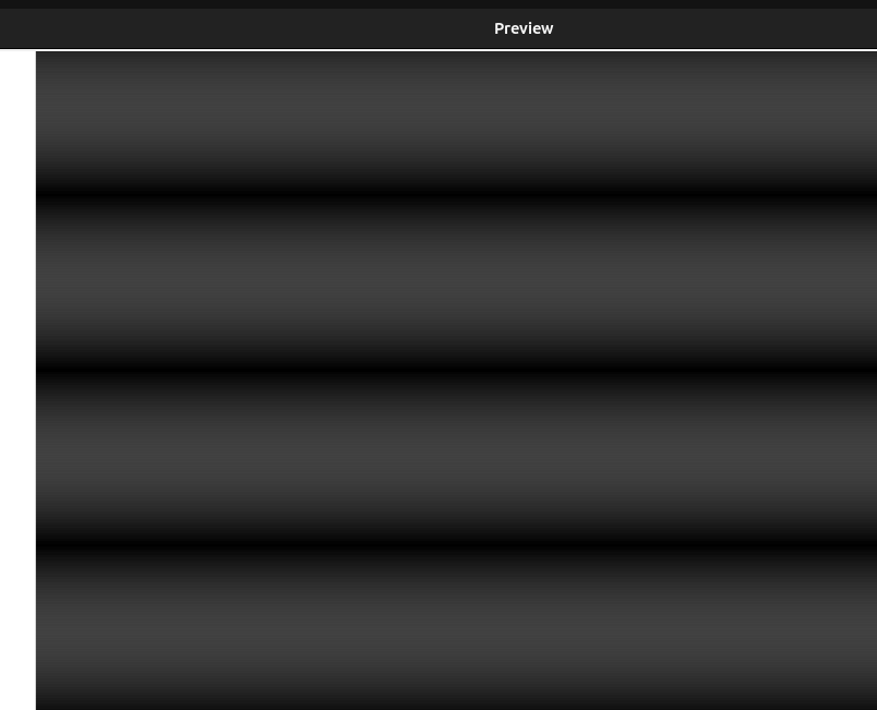
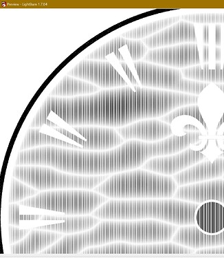
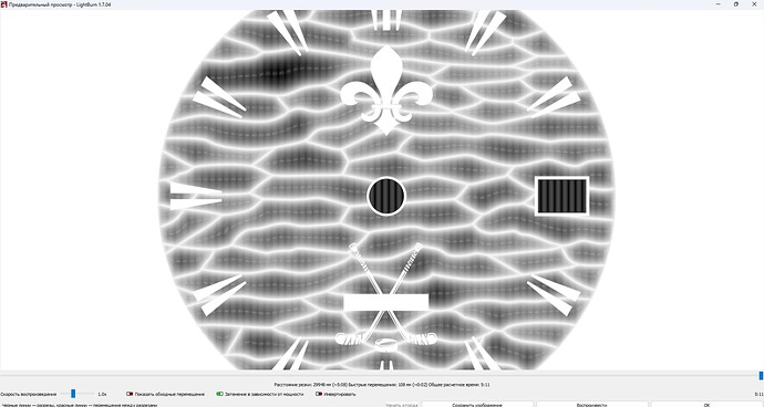
Open the image in preview. engraving at 90 degrees
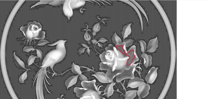
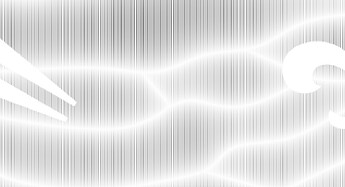
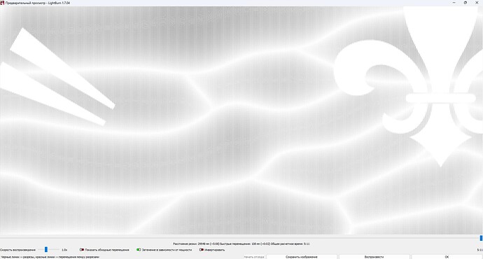
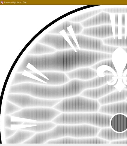
In the picture, I have highlighted some places in red, light stripes are visible. Based on what was described above about engraving in shades of gray, light stripes indicate that the engraving in these places will be weaker.
These light spots should have been the darkest according to the drawing.
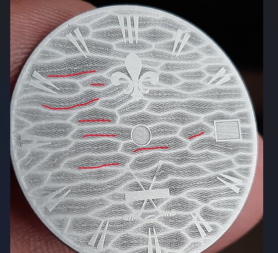
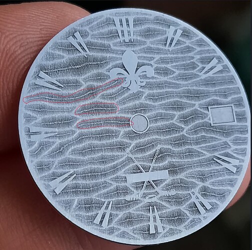
Now let’s see how this will manifest itself when engraving on metal:
As you can see, these light areas that were in the preview also appeared during engraving. But these lines are not in the original file.
Now, let’s do another experiment.
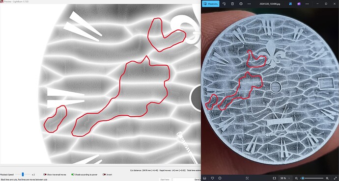
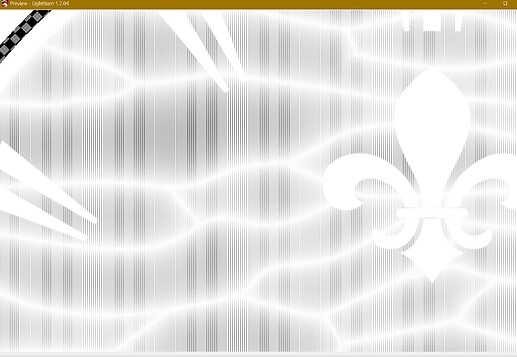
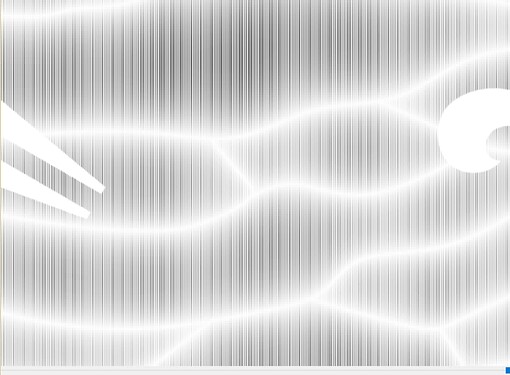
Let’s change the engraving direction to 0 degrees.
Look at the preview and the finished engraving. I marked the problem areas in red. And the picture of the artifacts has changed:
Now let’s conduct the third experiment.
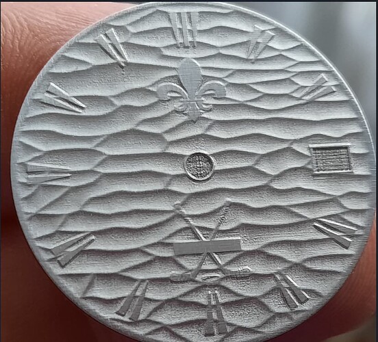
In the third experiment we will make 3D engraving using the 3D Slicer mode:
This was done with the same parameters as the grayscale engraving of the same image.
As a result, we see the absence of any artifacts that appeared during engraving in shades of gray. From this we can conclude that the resolution of the drawing, the density with which it is engraved, the features of the equipment, etc. are not relevant.
Now let’s make an engraving in shades of gray with the same parameters in the ezcad program
Get the result without the above artifacts:
This also indicates that the problem is not with the hardware or files.
Let’s do one more experiment.
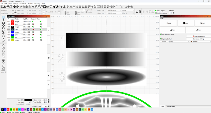
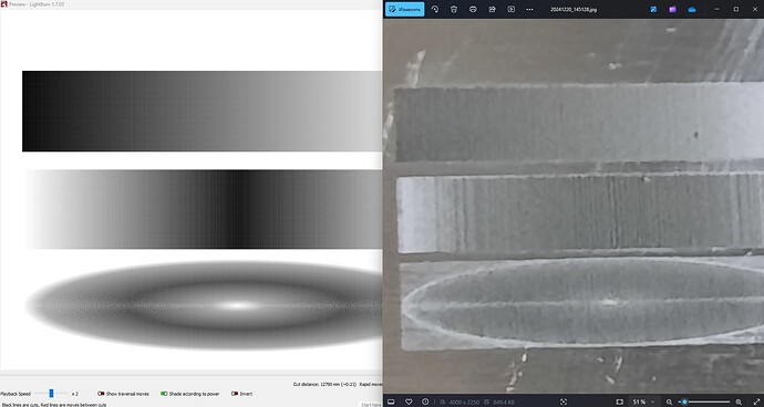
I took three objects and made them with different fills.
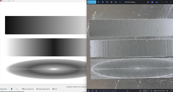
The first object is a simple transition from light to dark. As we can see, there are no artifacts either in the preview or during engraving.
The second object is a complex fill. From light to dark and back to light. Here, artifacts in the form of vertical stripes begin to appear, but they are weakly expressed.
The third object is a more complex oval fill from light to dark and back to light. It contains the largest number of artifacts, which are clearly visible during engraving and are clearly visible in the preview mode.
I hope I have given a detailed overview of the problem. And I want to get an answer from the developers: how can this problem be solved?
