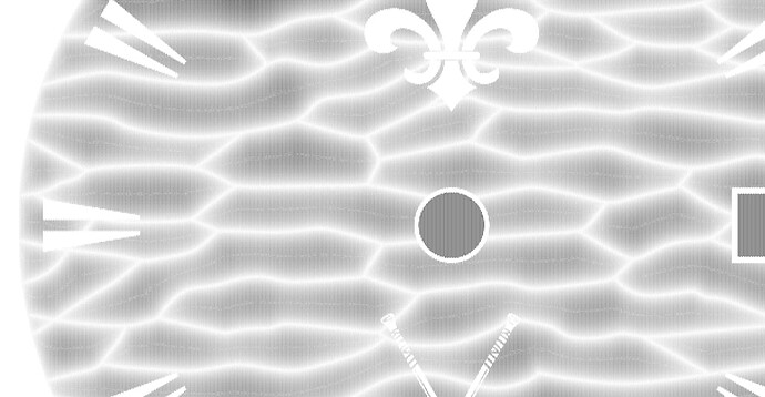
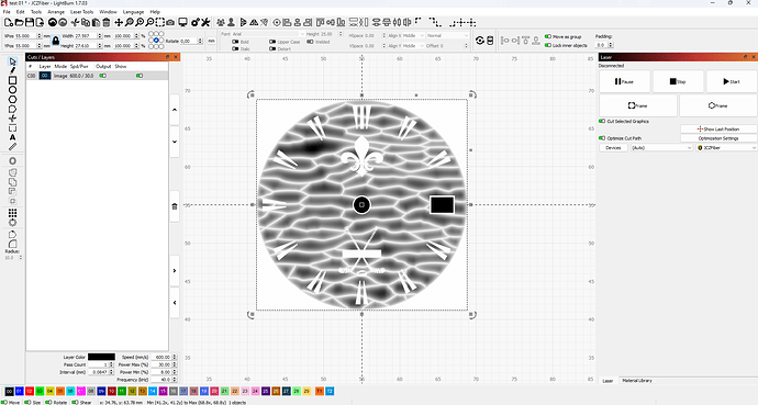
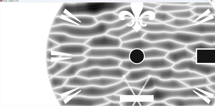
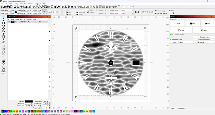
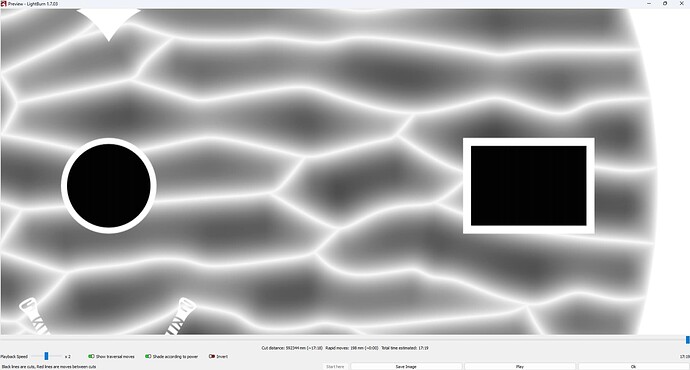
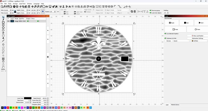
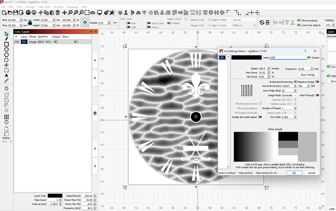
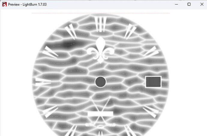
I have rewritten the problem in more detail below the link. Go to it, everything is described there again and in more detail:
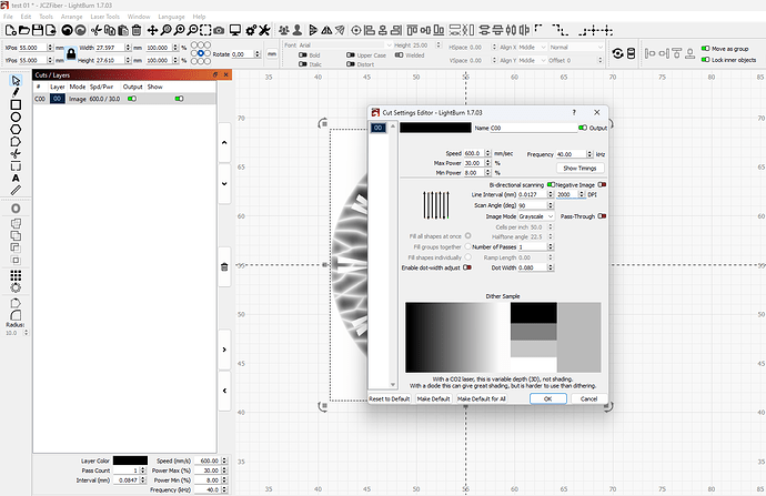
Your line interval is .0101 mm / 2515 DPI. What kind of machine setup do you have? Is it really capable of resolving at that resolution?
What is the DPI of the input image?
The artifacts you’re getting in the Preview look like they may be scaling artifacts from either the DPI value or disparity between source and target DPI. If you change the DPI setting do the patterns in the artifacts change?
This is the minimum possible, at which other artifacts do not arise. I raised this issue earlier.
The problem of engraving in grayscale - LightBurn Software Questions - LightBurn Software Forum
If you reduce the resolution of the drawing, it does not help. Plus I need This resolution, at this resolution I can get the effects I need. Reducing this resolution does not allow me to get the engraving effects I need
0.04мм/635DPI
The approach you’re describing seems more like a workaround that’s not addressing the fundamental issues with the mismatch in 4 things:
- input DPI
- input image dimensions
- DPI setting
- output image dimensions
I’d suggest this approach since you have control of the original model:
- Determine the resolvable line interval/DPI of your machine. Let’s assume it’s 300 DPI.
- Determine the desired dimensions of the output. Let’s assume 20x20 mm.
- Directly generate the grayscale image from the 3D model at 20x20mm at 300 DPI.
- Set LightBurn cut setting to 300 DPI
- Test
What are the results?
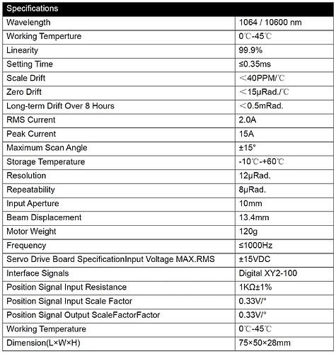
I don’t have a workaround. As far as I understand, you haven’t encountered fiber lasers. First, here are the specs of the equipment:
If I make all the calculations for my lens (Facal distance and so on), then the resolution on the plane between two lines will be approximately (rounded up) 0.003 mm.
If I make an engraving of two lines with a distance between them of 0.024 mm at low power, then under a microscope, they will be quite distinguishable.
You are trying to bind to the resolution of the equipment, but as I showed at the very beginning, the problems are visible even at the preview stage, which the resolution of my equipment does not affect in any way. I can change the original resolution of the drawing and this does not affect the appearance of these artifacts. Considering that the normal standard resolution with which I work is 0.015 mm and 0.001 mm and the program together with the machine performs it calmly, except for the grayscale mode. Other programs do not have this problem.
I may not have been clear enough earlier. The resolvable DPI is only tangentially relevant. I was asking to confirm the actual resolvable DPI only to determine a target value. The specific value is largely not relevant. Your calculated DPI of over 8000 still seems quite high but the actual value is not relevant other than that going higher than resolvable is not necessarily helpful at best, possibly harmful at worst, and possibly obfuscating issues in other cases.
The primary point that I was trying to make is that the issues you’re seeing are likely scaling artifacts and illustrating strategies for minimizing or eliminating variables that would affect that scaling. All scaling algorithms have tradeoffs and limitations. It’s about understanding them and working with those limitations.
The problem does not depend on the original resolution of the drawing or the resolution in the engraving settings. It disappears if I make the drawing larger. Either in Lightburn, or even the drawing itself when saved. But this solution does not suit me.
For better understanding:
Here is an image with a resolution of 2000 dpi (size in mm 27.6 x 27.6 mm). In this case I get artifacts, as shown above.
If I change the image in the Lightburn program to a size of 95 x 95 mm, while keeping all other parameters unchanged. The problem disappears
Let’s reduce the resolution of the image when saving to a resolution of 300 dpi and leave the size 27.6 x 27.6 mm (this is the size of the workpiece)
we will get the same picture as above
That’s interesting.
Some questions:
- How are you generating your input images?
- What format are they in?
- What was the original native size of the 2000 DPI image? The one you started at 27.6x27.6 mm.
- What is your final target size?
If you are changing size you are scaling irrespective of DPI setting.
Looks like to me that the issue may be introduced at the final laser path generation stage.
The image generation method does not matter. This problem is observed when generating directly from a 3D modeling program and generating an image through CorelDraw and other programs. Before writing here, I conducted a bunch of tests.
I tried the image format jpg in png.
As I wrote above, my workpiece is 27.6 mm in size.
I have several fiber laser machines with different software. I have been working with fiber lasers since 2006. And this problem is observed only when working in lightburn. I think the problem is most likely in lightburn itself, not the image.
I do not want to take the conversation in another direction here. In my opinion, this is a good product with excellent potential for the future.
But there are a number of questions to which I would like to receive a specific answer.
You didn’t mention the lens you are using.
My shortest lens (F100mm) has a spot size of ~16 microns (0.016mm), any attempt for resolution greater than your spot size can induce these types of patterns. For the F100mm lens it’s about 1587dpi. For my F254mm lens the spot size is about 30 microns, lowering possible resolution to about 847dpi.
I think you should try to use 3dslice, instead of grayscale. 3dslice is set up to no leave some of the things I think you’re using… it’s also based on 256 passes.
You’re best resolution is limited by the lens spot size. If you go over the same area multiple times, you can also induce this type of results.
Just a suggestion – Good luck
![]()
I will repeat myself once again. These artifacts are shown in the preview. And they are engraved on the product in the same way. If you reduce the dot density, nothing changes. I described this in detail above and attached screenshots. I also attached a photo of what happens when engraving in shades of gray in another program and these artifacts are not there. I cannot use a 3D slicer in the task where I use it. I do not need it for 3D. It just looks more visual in the case of 3D engraving. That is why I showed this example.
Now regarding the lens. I use beam overlap when engraving and this type of engraving does not cause artifacts in any way, but allows for a smooth, almost polished surface on hardened materials, when making stamping matrices. I cannot publish examples of these works.
But I can bet that these artifacts are not caused by poor imaging or lack of resolution of the equipment.
To use beam overlap, you have to understand how it’s working on the material … You seem to have a handle on this, so I won’t pursue it any further, just a suggestion.
You see the artifacts because the preview shows where it will lase, not the results of the lasing on the material. If you see them in the preview, it’s likely you’ll see them in the finished product.
I suggested 3dslice as most people have issues getting a grayscale to work as they’d like.
Good luck
![]()
Nice and fine dials.
.
As I see it, now it´s holydays … In “boxes” we have less decimal places accepted and I hope no internal changes so with another PC I would install a fresh Lightburn 1.4.03 or 1.6.03 and set up all settings device drivers manually then test.
https://release.lightburnsoftware.com/LightBurn/Release/
Have you used this exact equipment with EZCAD and achieved results consistent with this claim?
Have you verified your timings and jump settings are correct?
Most importantly - galvanometers (and the board itself that controls them) have a specific limit to the number of addressable positions for each galvo. I suspect you’re up against that hard limit of the actual resolvable positions for your hardware, and that causes LightBurn to sample two identical mirror positions when outputting code to your laser due to your extreme DPI settings.
This is one potential explanation for why you are seeing errors that compound across your part - because those areas are getting etched twice. Not because LightBurn can’t do it - but because your hardware cannot, and LightBurn does its best to accommodate.
Your answers to the above questions will help us determine if this is the case. Specific make and model information for your galvo with also help.
It sounds like the bit width of the variables in Lightburn is not sufficient to handle the precision you are looking for in the scaling/code generation process.
It would be reasonable to expect that the developers may have only expected to handle resolutions of less than 1012 DPI when they wrote the original code…
It is pointless to talk about the machine’s capability when the problems are evident in the software generated preview.
AFAICT, LightBurn simulates the hardware response, using what it knows of the machinery. An accurate simulation includes the appropriate hardware limitations / dynamic range / whatever and presents those on the screen, so you know what to expect.
The simulation does not include the actual material response to the laser, but in terms of power applied per resolvable pixel, it may be showing exactly what the laser will do, limitations and all.
My point is: do the algorithms in Lightburn have enough headroom to simulate the precision being asked?
Do they acept the machine resolution that the user is nominating?
Why do artifacts appear at extreme resolutions, when they do not appear at low resolutions?
The ‘possible resolution’ is 65535 x 65535 as far as the EZCAD2 board goes.
If this is compounded by using a long lens and a small part size, I could see this being the issue. What length of lens do you have in your machine? What is your working area? Some simple match can find the theoretical maximum DPI
I conducted my experiments on the same equipment with the programs Lightburn and Ezcad
The tinctures are the same
I did another experiment. I took another computer, installed a test version of the program on it and specified other equipment.
But the preview had the same problems.
Therefore, if we follow your logic, they should disappear or be different, but not be identical, because the equipment is different
I also sent an email in which I attached a file with this image. This was a few days ago.
Thank you, you are the only one who understood what I am writing about. Everyone else is looking for a problem in the equipment
